

On-die termination device
- Summary
- Abstract
- Description
- Claims
- Application Information
AI Technical Summary
Benefits of technology
Problems solved by technology
Method used
Image

Examples
first embodiment
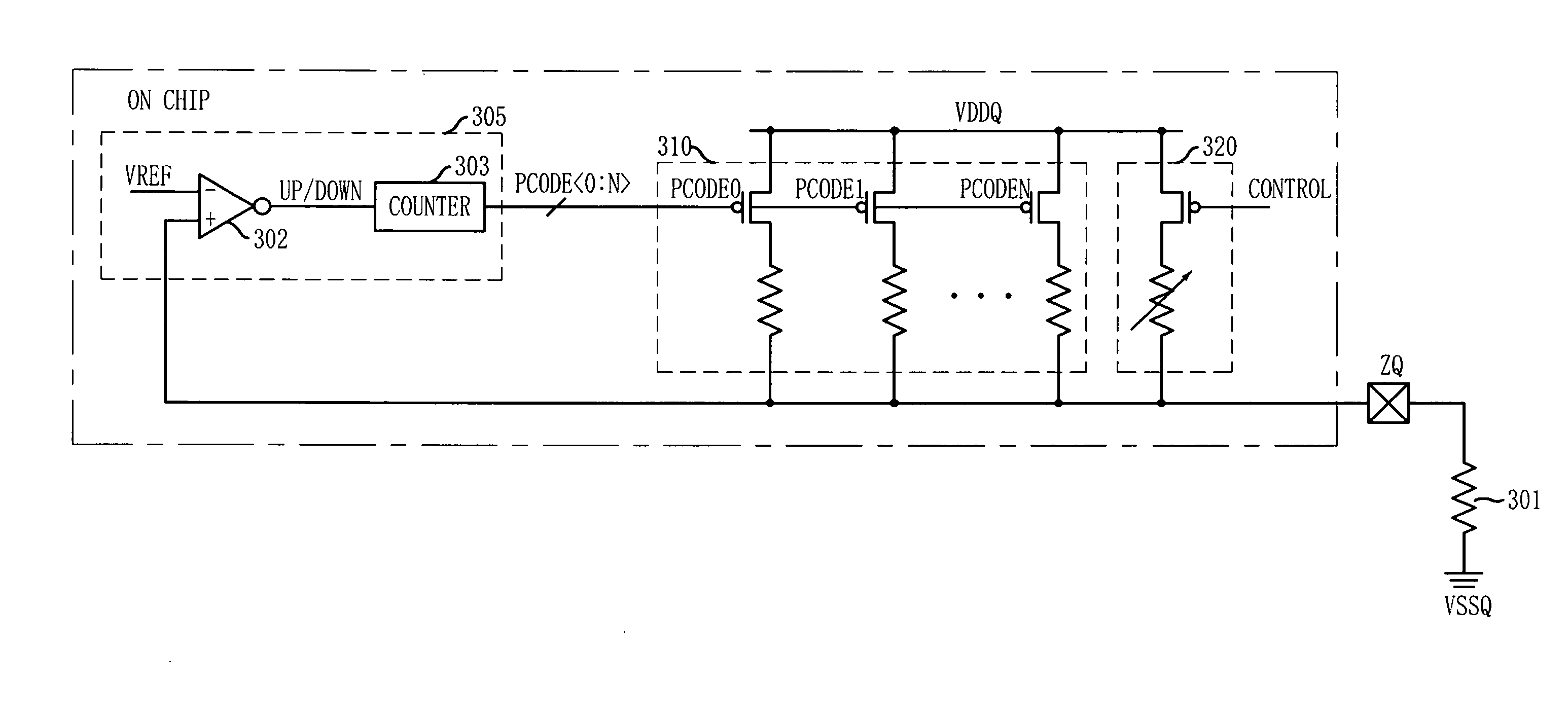
[0051]FIG. 5 is a block diagram of a calibration circuit having only a pull-up resistor unit in accordance with the present invention.
[0052] The calibration circuit of the ODT device in accordance with the first embodiment of the present invention includes a code generator 305, a plurality of pull-up calibration resistors 310, and a reference resistor 320.
[0053] The code generator 305 generates pull-up calibration codes PCODE in response to a ZQ node voltage and a reference voltage VREF (generally, ½VDDQ). The code generator 305 may include a comparator 302 configured to compare the reference voltage VREF and the ZQ node voltage with each other, and a counter 303 configured to count the pull-up calibration codes PCODE depending on the comparison result of the comparator 302.
[0054] The plurality of pull-up calibration resistors 310 are turned on / off in response to the pull-up calibration code PCODE, and are connected to the ZQ node in parallel.
[0055] The reference resistor 320 is ...
second embodiment
[0072]FIG. 8 is a block diagram of a calibration circuit having pull-up and pull-down resistor units in accordance with the present invention.
[0073] A calibration circuit of the ODT device in accordance with the second embodiment of the present invention includes a first code generator 502 and 503, a second code generator 504 and 505, a plurality of first pull-up calibration resistors 510, a first pull-up reference resistor 520, a plurality of second pull-up calibration resistors 530, a second pull-up reference resistor 540, a plurality of pull-down calibration resistors 550, and a pull-down reference resistor 560.
[0074] The first code generator 502 and 503 generates pull-up calibration codes PCODE in response to a ZQ node voltage and a reference voltage VREF, and the second code generator 504 and 505 generates pull-down calibration codes NCODE in response to a voltage of a first node NODE B and the reference voltage VREF.
[0075] More specifically, the first code generator 502 and ...
PUM
 Abstract
Description
Claims
Application Information