Adaptive deformable mirror for compensation of defects of a wavefront

Active Publication Date: 2011-09-15
FRAUNHOFER GESELLSCHAFT ZUR FOERDERUNG DER ANGEWANDTEN FORSCHUNG EV +1
View PDF6 Cites 7 Cited by
  • Summary
  • Abstract
  • Description
  • Claims
  • Application Information

AI Technical Summary

Benefits of technology

[0008]The adaptive mirror according to the invention, in its simplest form, consists of a thin substrate layer, on the first surface of which a reflective layer is applied and the second surface of which is connected to at least one actuator. According to the invention, the substrate layer has a thickness of less than or equal to 1,000 μm. Such a small thickness of the substrate layer is necessary in order to avoid or at least to minimise thermal deformations due to the high power of the incident radiation. Since the heat expansion is proportional to the substrate thickness, the result, from the condition that the thickness of the substrate layer is 1,000 μm or less, is merely a small thermal deformation. Furthermore, the heat expansion coefficients of the materials used for the reflecting layer and the substrate layer are coordinated. Thermal deformations which neve

Problems solved by technology

Because of the high power of the incident radiation and the absorption thereof, the result can be deformations of the mirror layer.
The previous state of the art demands high manufacturing and mounting complexity in order to connect the actuators or the active layers correspondingly to the mirror surface and/or in order to produce permanently the desired curvature of the mirrored layer.
Furthermore

Method used


Image

  • Adaptive deformable mirror for compensation of defects of a wavefront
  • Adaptive deformable mirror for compensation of defects of a wavefront
  • Adaptive deformable mirror for compensation of defects of a wavefront

Examples


Example

[0031]A few examples of adaptive mirrors and arrangements according to the invention are provided in the following. There are shown:

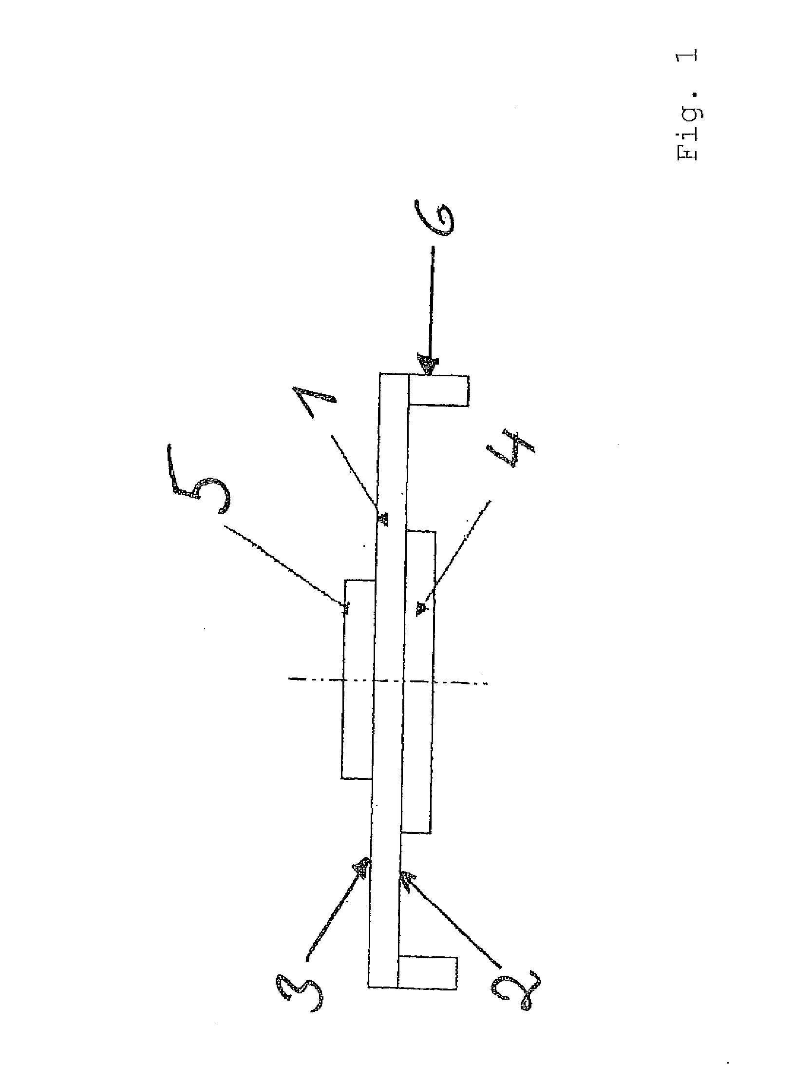
[0032]FIG. 1 a basic construction of an adaptive mirror according to the invention,

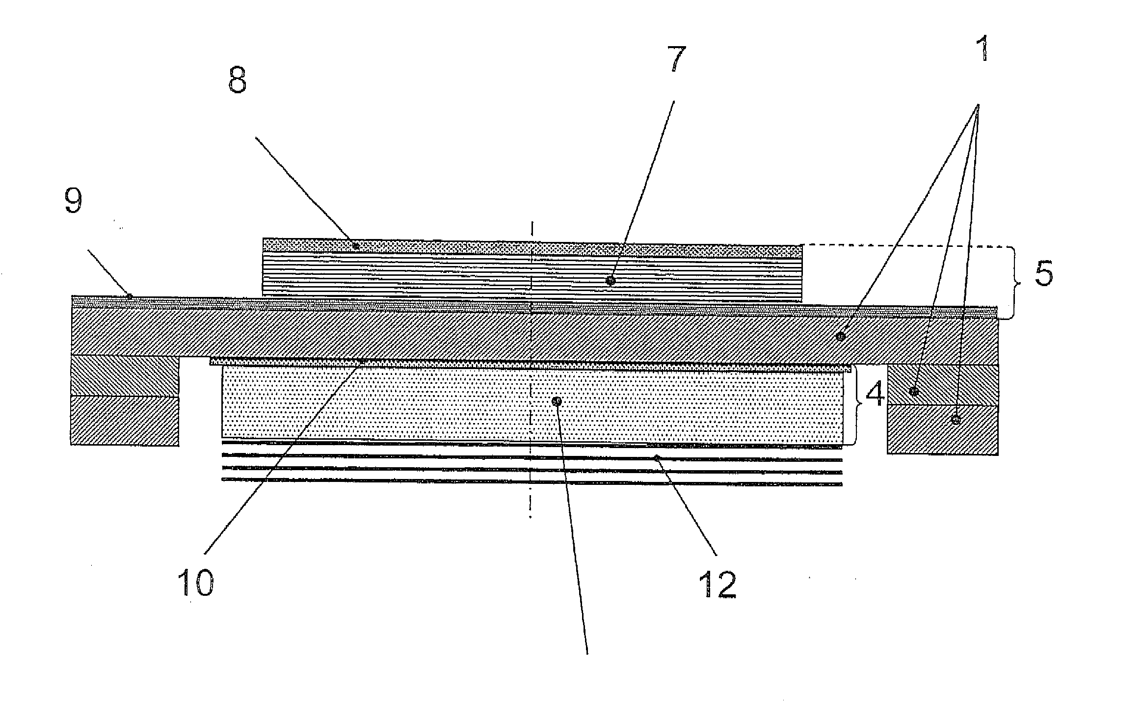
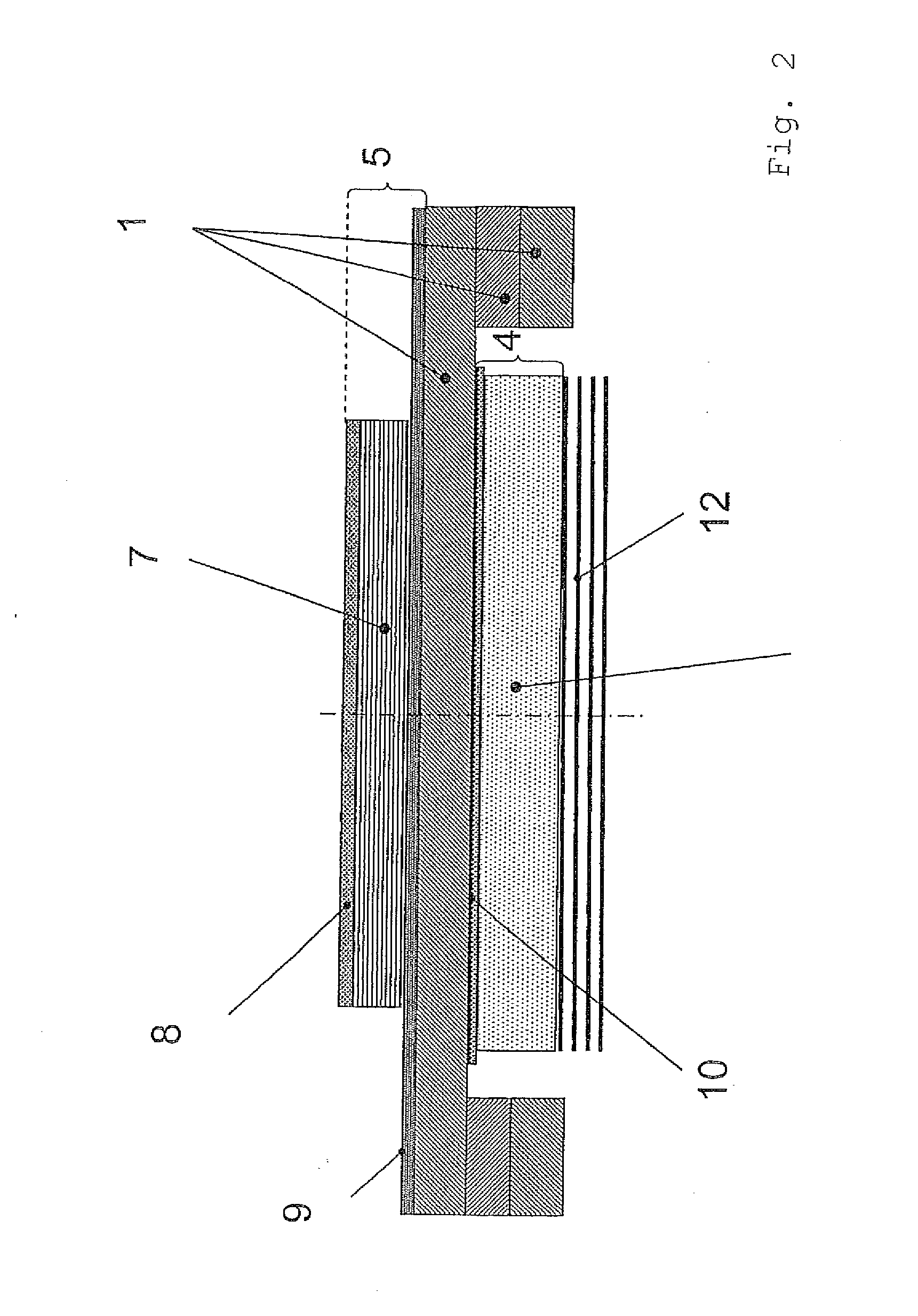
[0033]FIG. 2 a construction of an embodiment of an adaptive mirror according to the invention, and

[0034]FIG. 3A-3D a plan view on an adaptive mirror with various actuation methods via differently disposed partial electrodes.

[0035]FIG. 1 shows the cross-section through an adaptive mirror as is described in the present invention. The same or similar reference numbers here thereby describe the same or similar elements in the following Figures.

[0036]The adaptive mirror is constructed from a substrate layer 1 which is at most 1,000 μm thick, on the first surface 2 of which a reflecting layer 4 and on the second surface 3 of which at least one actuator 5 is applied. At the edges of the substrate layer 1 on the first surface 2 thereof, a mounting 6 is fitted and has for LTCC the...


PUM

PropertyMeasurementUnit
Thicknessaaaaaaaaaa
Thicknessaaaaaaaaaa
Thicknessaaaaaaaaaa

Abstract

The present invention relates to the production of an adaptive deformable mirror for compensation of defects of a wavefront.

Description

PRIORITY INFORMATION[0001]The present invention is a 371 National Phase Application of International Application No. PCT / EP2009 / 001967, filed on Mar. 17, 2009, that claims priority to German Application No. DE 102008014615.3, filed on Mar. 17, 2008. Both applications are incorporated herein in their entireties.BACKGROUND OF THE INVENTION[0002]The present invention relates to the production of an adaptive deformable mirror for compensation of defects of a wavefront.[0003]Adaptively deformable mirrors are used in various fields of optics, thus e.g. in terrestrial or extraterrestrial applications but also in experiments with electromagnetic radiation with high power, as is emitted by high-power lasers and / or high-power laser processes or in experiments with low or extreme ultraviolet radiation.[0004]In particular for use with low or extreme ultraviolet radiation, various embodiments of adaptive mirrors have been developed. The basic idea resides in a mirror surface being deformed by me...

Claims


Application Information

Patent Timeline
IPC IPC(8): G02B7/185B05D5/06B05D5/00C23C16/50B32B37/02B32B37/14B32B38/04C25D5/54
CPCY10T156/1052G02B26/06
Inventor BRUCHMANN, CLAUDIABECKERT, ERIKPESCHEL, THOMASDAMM, CHRISTOPHGEBHARDT, SYLVIA
Owner FRAUNHOFER GESELLSCHAFT ZUR FOERDERUNG DER ANGEWANDTEN FORSCHUNG EV
Why Eureka
Try Eureka