[0022]In the discussion that follows, reference is made to one or more embodiments shown in the drawings. The invention, however, is not intended to be limited to the embodiments shown and described. To the contrary, the invention is intended to encompass additional equivalents and variations, as should be understood by those skilled in the art.
[0023]In the following description of the figures, terms such as above, below, to the left, to the right, in front, behind etc. refer only to the exemplary illustrations and position of the apparatus and its constituent parts selected in the respective figures. These terms are not to be understood as restrictive, that is to say these relationships can change in different operating positions or by virtue of mirror-image symmetrical design or the like.
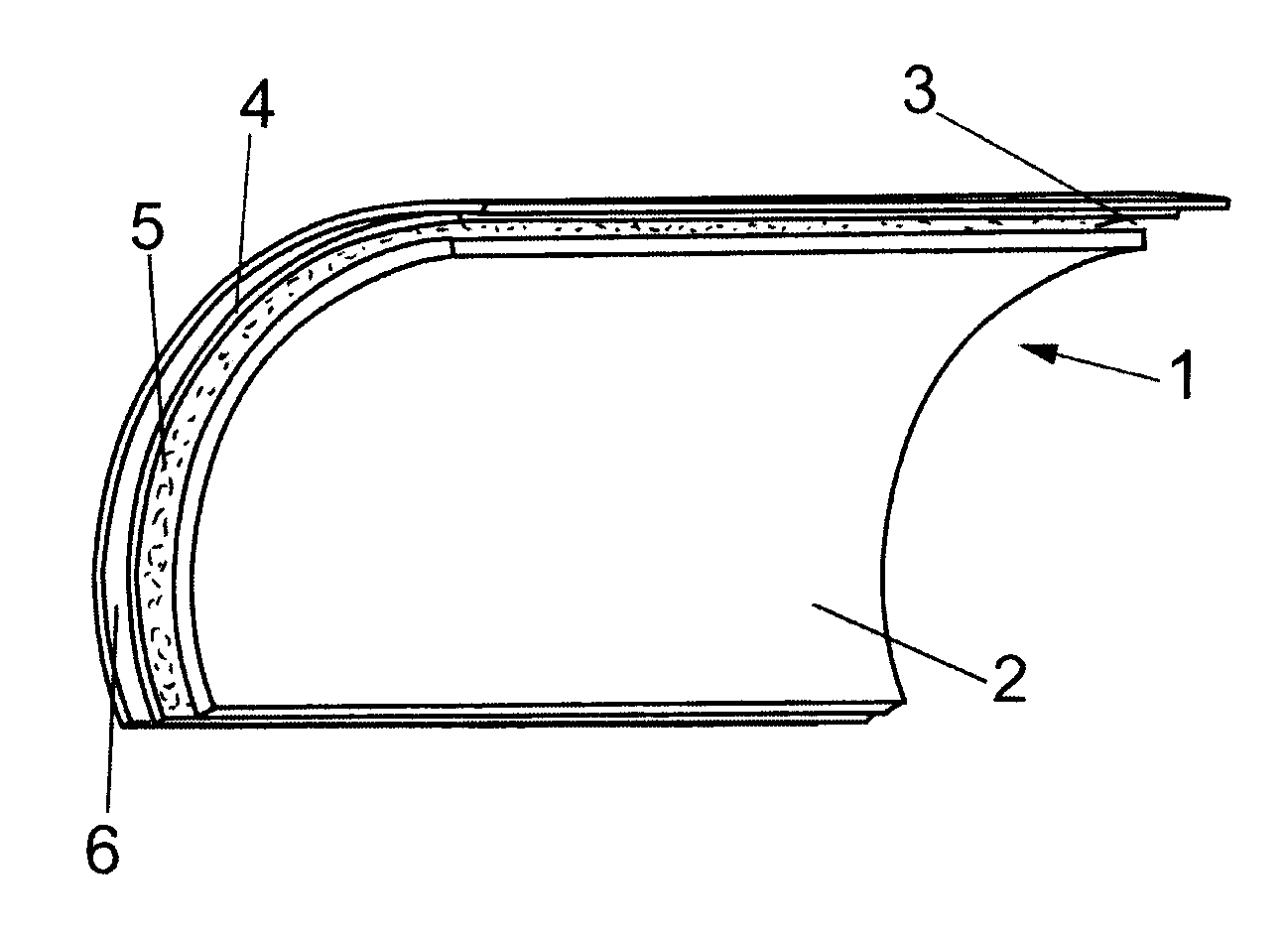
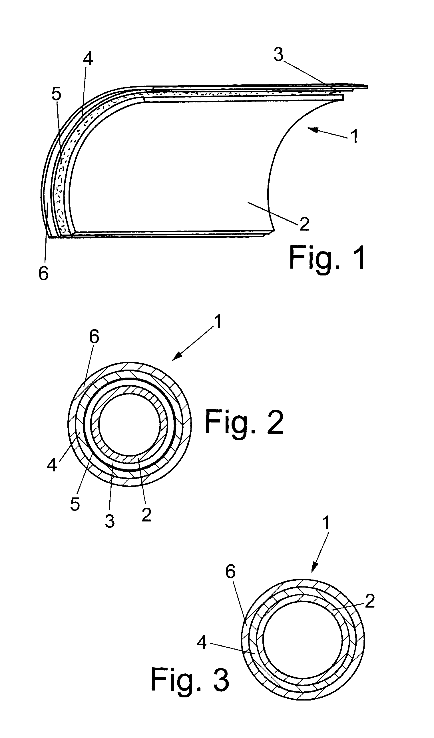
[0024]FIG. 1 shows a preferred embodiment of the apparatus for generating electrical power from the waste heat of a motor-vehicle internal combustion engine. The apparatus has a double-walled pipe 1 with a first inner pipe wall 2 and a second outer pipe wall 6 and also a thermoelectric generator 4 which is arranged in an air gap 3 between the first inner pipe wall 2 and the second outer pipe wall 6. During operation of the motor-vehicle internal combustion engine, a medium which transports waste heat flows through the pipe 1. For the purpose of generating power, the first inner pipe wall 2 serves the thermoelectric generator 4 as a high-temperature source and the second outer pipe wall 6 as a low-temperature source. It is also feasible for only a portion of the pipe 1 to be of double-walled design, with the thermoelectric generator 4 being arranged in the double-walled region of the pipe, as described above.
[0025]The pipe 1 is preferably an exhaust pipe and the medium which transports waste heat is preferably an exhaust gas from the motor-vehicle internal combustion engine. The pipe 1 is particularly preferably a component piece of the exhaust system of a motor vehicle between an exhaust manifold and a catalytic converter, in which component piece the exhaust gas from the exhaust manifold is passed to the catalytic converter during operation of the motor-vehicle internal combustion engine.
[0026]The task of the air gap 3 between the pipe walls 2, 6 of the double-walled pipe is to insulate the inner pipe, as a result of which heat exchange between the exhaust gas and the external air, and therefore cooling of the exhaust gas, is reduced. In this way, an operating temperature which is required for the catalytic converter can be reached as quickly as possible, in particular during the cold-start phase.
[0027]The second outer pipe wall 6 can be cooled by a cooling medium on that side which is averted from the first pipe wall 2, in particular by the ambient air. Cooling using another medium, for example water, is likewise feasible.
[0028]In the plan view shown in FIG. 2, the thermoelectric generator 4 is fixed only to the second outer pipe wall 6. In this embodiment, heat is transferred between the first pipe wall 2 and the thermoelectric generator 4 mainly by thermal radiation, whereas heat is transferred between the second pipe wall 6 and the thermoelectric generator 4 by thermal conduction. One advantage of this embodiment is that the thermoelectric generator 4 is not firmly connected to the high temperature side, that is to say to the inner pipe 2. The different expansions in length of the components of the thermal generator 4 caused on account of unequal coefficients of expansion can be easily compensated for in this way. A further advantage is that thermal generators can also be used in the high-temperature range of an exhaust manifold, without the said thermal generators having to be designed for this temperature range.
[0029]In order to intensify the absorption of the thermal radiation emanating from the inner pipe 2, that side of the thermoelectric generator 4 which faces the first pipe wall 2 can be provided with a, for example, black absorption layer.
[0030]In the plan view of another embodiment shown in FIG. 3, the thermoelectric generator 4 is fixed to the first pipe wall 2 and the second pipe wall 6. In this embodiment, heat is transferred between the first pipe wall 2 and the thermoelectric generator 4 and between the second pipe wall 6 and the thermoelectric generator 4 by heat conduction. This embodiment is suitable for the use of thermal generators which are designed for the high-temperature range (>400° C.). The advantage of this embodiment is that the introduction of heat is improved and, at the same time, a higher usable temperature difference is available compared to the use of thermal radiation in the first embodiment.
[0031]In addition to the primary function of providing electrical energy, three further functions can be realized by the apparatus, it being possible to electrically adjust these functions using a corresponding logic system. To this end, the thermoelectric generator 4 is preferably coupled to an electronic control system.
[0032]With the aid of the electronic control system, the apparatus is suitable for feeding the electrical power, which is generated by the thermoelectric generator 4, to a battery or an on-board power supply system of the motor vehicle, preferably via an intermediate electric circuit.
[0033]In addition to generating electrical energy, the thermoelectric generator 4 can alternatively be used for temperature control which can be realized by virtue of a corresponding electrical circuit, for example with power resistors. This controllable cooling function is critical particularly during full-load operation, so that overheating of the catalytic converter can be counteracted in a targeted manner.
[0034]The thermoelectric generator can be actively used as a heat source or as a cooling unit in the apparatus by utilizing the Peltier effect. In this case, the application of an electric current produces a heat flow which heats or cools the first inner pipe wall 2. Active temperature control can also be realized in this way. Corresponding switchover to this mode is the task of the intermediate circuit or the electronic control system, triggered by an external control signal for example.
[0035]The electronic control system is further suitable for interrupting an electrical connection between an electrical load, which is coupled to the electronic control system, and the thermoelectric generator 4 as a function of the temperature of the exhaust gas which flows through the exhaust pipe 1.
[0036]At an excessively low exhaust-gas temperature, no more current flows through the thermoelectric generator 4. Therefore, energy is also no longer converted, as a result of which less heat is drawn from the inner pipe 2. Corresponding switchover to this mode is the task of the intermediate circuit. The electronic control system is preferably coupled to a temperature sensor for the purpose of measuring the exhaust-gas temperature. As an alternative, the temperature can also be reconstructed from the generator voltage.
[0037]During operation, a high-temperature source is initially generated on that side of the thermoelectric generator 4 which faces the first pipe wall 2 by conducting the medium which stores waste heat through the pipe 1 in order to generate electrical power from the waste heat of a motor-vehicle internal combustion engine having an above-described apparatus. In this case, some of the heat is transferred to the material of the first pipe wall 2 and the first pipe wall 2 is heated in the process. The low-temperature source is generated on that side of the thermoelectric generator 4 which faces the second pipe wall 6 by cooling that side of the second pipe wall 6 which is averted from the thermoelectric generator 4 using a cooling medium, in particular the ambient air. Using the temperature gradients generated as a result, the waste heat which is transmitted to the first pipe wall 2 is converted into electrical power by the thermoelectric generator 4.
[0038]In addition, the temperature of the exhaust gas of a motor-vehicle internal combustion engine can be actively controlled with an above-described apparatus having an electronic control system. In this case, the exhaust gas is first conducted through the pipe 1. This heats the first pipe wall 2. If the thermoelectric generator 4 is now supplied with power in such a way that heat is conducted away from that side of the thermoelectric generator 4 which faces the first pipe wall 2, the thermoelectric generator 4 serves to additionally cool the exhaust-gas stream in this manner of operation. If the thermoelectric generator 4 is supplied with power in such a way that heat is passed to that side of the thermoelectric generator 4 which faces the first pipe wall 2, the thermoelectric generator 4 serves to heat the exhaust-gas stream in this manner of operation, and this is useful, in particular, in the warm-up phase of the motor-vehicle engine.