Electrical connection element

Inactive Publication Date: 2020-12-31
STAUBLI ELECTRICAL CONNECTORS AG
View PDF0 Cites 0 Cited by
  • Summary
  • Abstract
  • Description
  • Claims
  • Application Information

AI Technical Summary

Benefits of technology

[0010]The two contact sections have preferentially been designed in each instance to be substantially the same or even identical to one another. The same applies to the two coupling-points. By this means, the advantage comes about that the transmission of current from the supply-point to the electrical conductor and from the electrical conductor to the electrode has the same characteristic in each instance. The two contact sections may also be different, depending upon the installation situation.
[0011]The electrical conductor preferably takes the form of a flexible cable. The flexible cable preferabl

Problems solved by technology

On the other hand, they are not maintenance-free, and wear occurs in the course of interchanging the secondary-circuit welding connectors.
Moreover, mounting by screw-type terminals or screws can have the result that the secondary-circuit joint is not optimally aligned and therefore an increased mechanical loadi

Method used


Image

  • Electrical connection element
  • Electrical connection element
  • Electrical connection element

Examples


Example

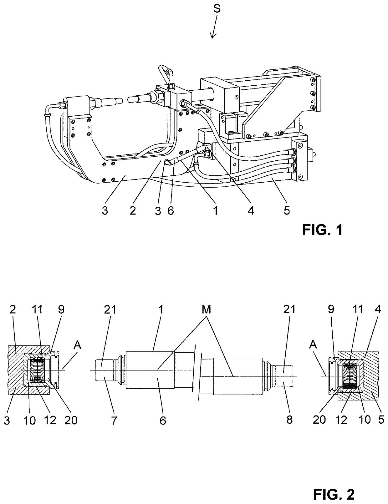
[0059]A welding device S is shown in FIG. 1. The welding device S includes an electrode 3 and a supply-point 5. The supply-point 5 supplies the electrode 3 with electrical energy. The welding device S according to FIG. 1 takes the form of C-type tongs. But the welding device S may also take the form of X-type tongs, or may have been designed in some other way.

[0060]An electrical connection arrangement 1 according to an embodiment of the present invention is arranged between the supply-point 5 and the electrode 3. The electrical connection arrangement 1 provides an electrical contact between the supply-point 5 and the electrode 3.

[0061]In the embodiment shown, the electrode 3 is a spot-welding device. But other welding devices may also be employed. The supply-point 5 may be a coupling of a transformer or of a similar supply element.

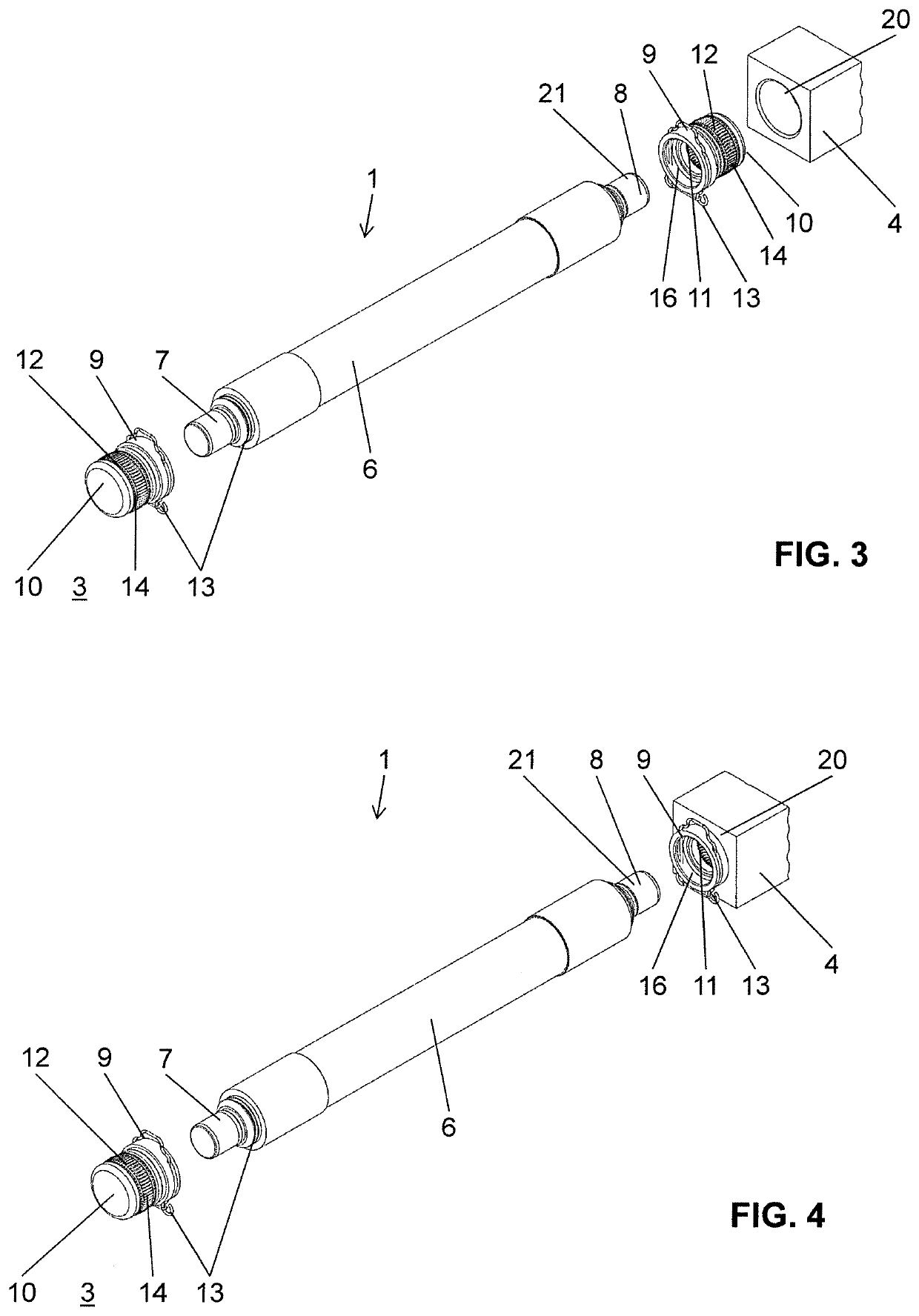
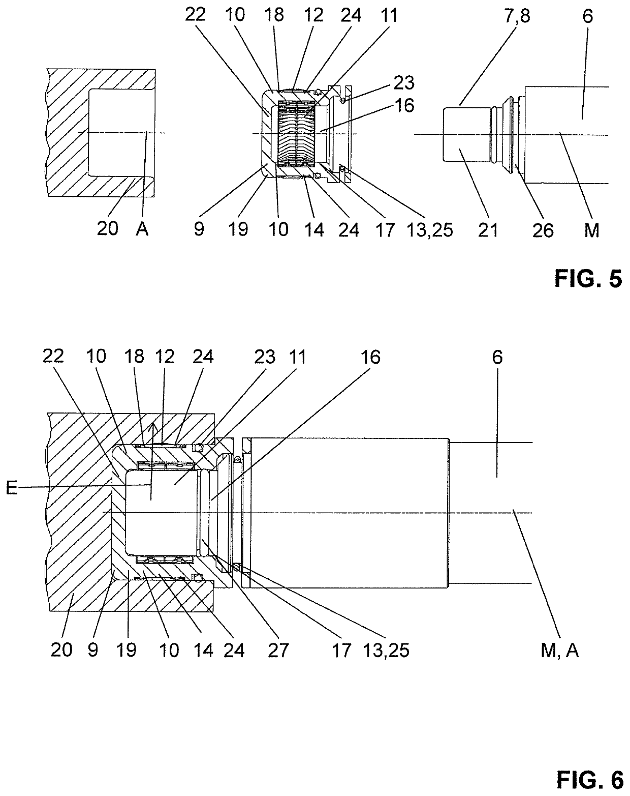
[0062]In the following, the electrical connection arrangement will now be explained in detailed manner with reference to FIGS. 2 to 8. FIGS. 2 to 6 show a...


PUM


Abstract

The invention relates to an electric connection assembly (1), in particular a secondary circuit welding connection assembly, which is used to provide an electric contact between an electrode-side connection point (2) of an electrode (3) and a supply-side connection point (4) of a supply point (5) of a welding device (S). The connection assembly (1) comprises a current conductor (6) with a first contact section (7) arranged at one end for connecting to the electrode-side connection point (2) and a second contact section (8) at the end opposite the first contact section (7) for connecting to the supply-side connection point (4). The first contact section (7) together with the electrode-side connection point (2) and the second contact section (8) together with the supply-side connection point (4) are in the form of a socket-plug connection (20, 21) and can be plugged together along a plug-in axis (A).

Description

TECHNICAL FIELD[0001]The present invention relates to an electrical connection element for the transmission of high currents, in particular for application in a welding appliance according to the preamble of claim 1.STATE OF THE ART[0002]Secondary-circuit welding connector arrangements in connection with welding devices have become known from the state of the art. Typically, such secondary-circuit welding connector arrangements, which are also designated as current hat, are connected to the welding appliance in electrically conducting manner by screw-type terminals or screws. But screw-type terminals or screws have various disadvantages. On the one hand, the interchanging of the secondary-circuit welding connectors is very elaborate. On the other hand, they are not maintenance-free, and wear occurs in the course of interchanging the secondary-circuit welding connectors. Moreover, mounting by screw-type terminals or screws can have the result that the secondary-circuit joint is not o...

Claims


Application Information

Patent Timeline
IPC IPC(8): B23K37/02H01R13/426H01R31/06
CPCB23K37/0258H01R13/426H01R13/17H01R31/06H01R13/005H01R13/18H01R13/187
Inventor HEILMANN, ALEXANDERHORNUNG, ALEXANDER
Owner STAUBLI ELECTRICAL CONNECTORS AG
Why Eureka
Try Eureka