System for minimizing coupling nulls

a coupling null and coupling technology, applied in the direction of subscriber station connection selection arrangement, transmission, indirect connection of subscriber station, etc., can solve the problems prone to detuning and other undesirable effects, and the implementation of the antenna arrangement is relatively complex. , to achieve the effect of reducing the size of the shield and reducing the far-field radiation

Inactive Publication Date: 2008-02-28
HID TEXTILE SERVICES SARL
View PDF4 Cites 32 Cited by
  • Summary
  • Abstract
  • Description
  • Claims
  • Application Information

AI Technical Summary

Benefits of technology

[0015]A system as described herein may reduce far-field radiation from an electro-magnetic source for compliance with local Electro-...

Problems solved by technology

However, a disadvantage of the system is that objects that do not rotate or otherwise change their orientation relative to a reading antenna many not be read reliably.
Additionally, implementation of the antenna arrangement...

Method used


Image

  • System for minimizing coupling nulls
  • System for minimizing coupling nulls
  • System for minimizing coupling nulls

Examples


Embodiment Construction

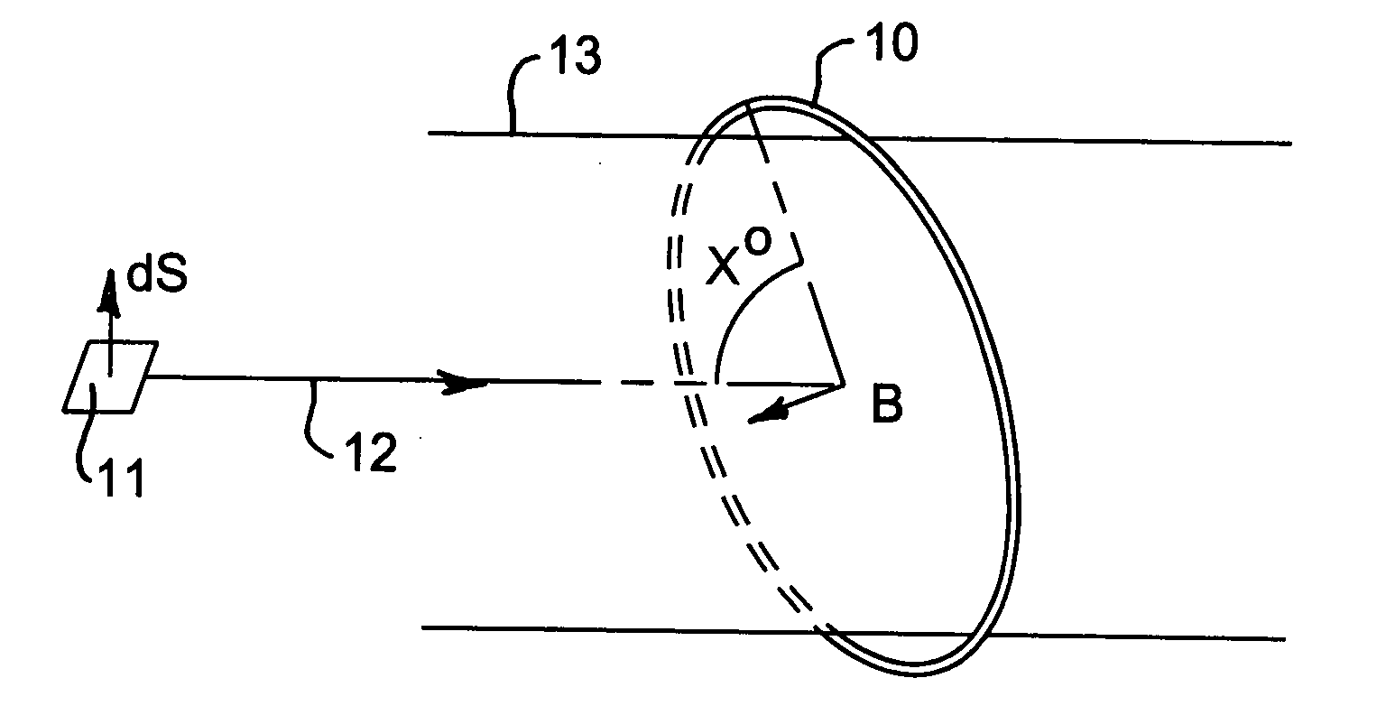
[0021]An example of an antenna loop 10 is shown in FIG. 1. In FIG. 1 the direction of movement through antenna loop 10 of an object 11 bearing an RFID tag is along axis 12 associated with forming cylinder 13. In FIG. 1 the angle x formed between the direction of movement 12 and the plane of loop 10 may fall within the range 010 is oriented in a direction (pâp, φaφ, zâz) where p#0 (oblique) and z#0 (aperture exists) then as magnetic flux density B at loop centre point is in the same direction, coupling to a randomly oriented tag relative to its axis of movement(âz) may be represented as a non-zero flux Ψ at some φtag, wherein Ψ is the angle between the magnetic field B and the tag's axis which is taken to point in a direction dS. Then

Ψ∝B·dS=Bp(Sxcosφtag+Sysinφtag)+Bφ(-Sxsinφtag+Sycosφtag)+BzSz=Bp(Sxcosφtag+Sysinφtag)+BzSzasBφmaybezerobutBp#0andBz#0#0forsomeφtag,asSx,Sy,andSzcannotallbesimultaneously0

[0022]Hence a single loop antenna 10 having its axis oriented with an oblique angle x...


PUM


Abstract

A system is disclosed for minimizing coupling nulls between an electromagnetic field derived from one or more sources and a plurality of randomly oriented RFID tags, wherein the electromagnetic field is rotated relative to the tags such that no tag is persistently located in a coupling null relative to the field. The source of the electromagnetic field may include a passive antenna or loop that changes its orientation relative to a direction of movement of the tags. The source of the electromagnetic field may further include an active antenna or loop that is electromagnetically coupled to the passive antenna or loop. A method for minimizing coupling nulls between the electromagnetic field and the randomly oriented tags is also disclosed.

Description

FIELD OF THE INVENTION[0001]The present invention relates to a system for avoiding or at least minimizing coupling nulls between an electromagnetic field derived from one or more sources and a plurality of radio frequency identification (RFID) tags. The system may include an object management arrangement wherein information bearing electronically coded RFID tags are attached to objects which are to be identified, sorted, controlled and / or audited. In particular the system may avoid or at least minimize coupling nulls between an interrogator which creates an electromagnetic interrogation field and the electronically coded RFID tags.BACKGROUND OF THE INVENTION[0002]The object management arrangement may include information passing between the interrogator and the electronically coded tags, which respond by issuing a reply signal that is detected by the interrogator, decoded and consequently supplied to other apparatus in the sorting, controlling or auditing process. The objects to whic...

Claims


Application Information

Patent Timeline
IPC IPC(8): H04B7/00
CPCH01Q7/00
Inventor LENEVEZ, YVES
Owner HID TEXTILE SERVICES SARL
Why Eureka
Try Eureka