Projection display apparatus

a technology of projection display and projection surface, which is applied in the direction of lighting and heating apparatus, waveguides, instruments, etc., can solve the problems of different shape of light valves and actual illumination of areas, and achieve the effect of improving light use efficiency and uniformity in illuminance distribution

Inactive Publication Date: 2008-02-28
MITSUBISHI ELECTRIC CORP
View PDF2 Cites 6 Cited by
  • Summary
  • Abstract
  • Description
  • Claims
  • Application Information

AI Technical Summary

Benefits of technology

[0010]In the present invention, the cross-sectional shape of the light intensity equalizing element is determined in accordance with: an ideal illumination area including an image forming area on a reflective light valve; an illumination area on the reflective light valve when a reference light intensity equalizing element is assumed to be used, the reference light intensity equalizing element being rectangular in a cross-sectional shape in a direction orthogonal to a central light ray; and the cross-sectional shape of the reference light intensity equalizing element. For this reason, according to the present invention, even when the image forming area on the reflective light valve cannot be vertically irradiated with light, the actual illumination area by the light, with which the reflective light valve is irradiated, can be made to approximately coincide with the ideal illumination area. Hence, there is produced the effect of improving light use efficiency and uniformity in an illuminance distribution.

Problems solved by technology

However, for example, when the incident surface (hereinafter referred to as a “surface to be illuminated” or an “image forming area”) of the light valve is not vertically irradiated with light, even if the cross-sectional shape of a light intensity equalizing element is made similar to the shape of the incident surface of the light valve, there is presented a problem that an area actually illuminated (hereinafter referred to as an “actual illumination area”) on the light valve is different in shape from the incident surface of the light valve.
This problem is often raised in a case where the incident surface of the light valve cannot be vertically irradiated with the light because of the construction of an optical system, for example, in a case where because of the use of a reflective light valve, a mirror for introducing light to the reflective light valve and a projecting optical system which magnifies and projects the light reflected by the reflective light valve are arranged adjacently to each other.

Method used


Image

  • Projection display apparatus
  • Projection display apparatus
  • Projection display apparatus

Examples


first embodiment

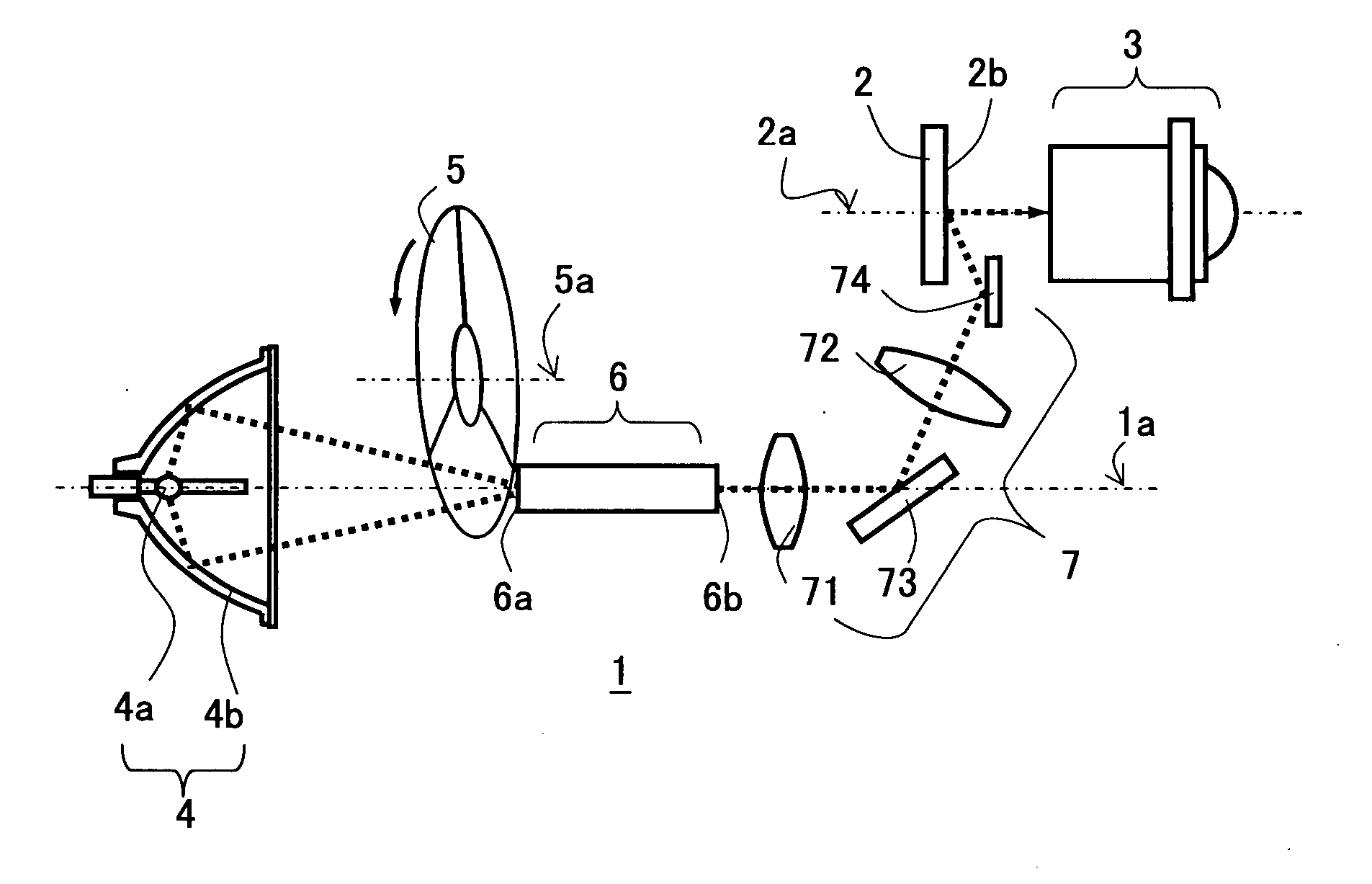
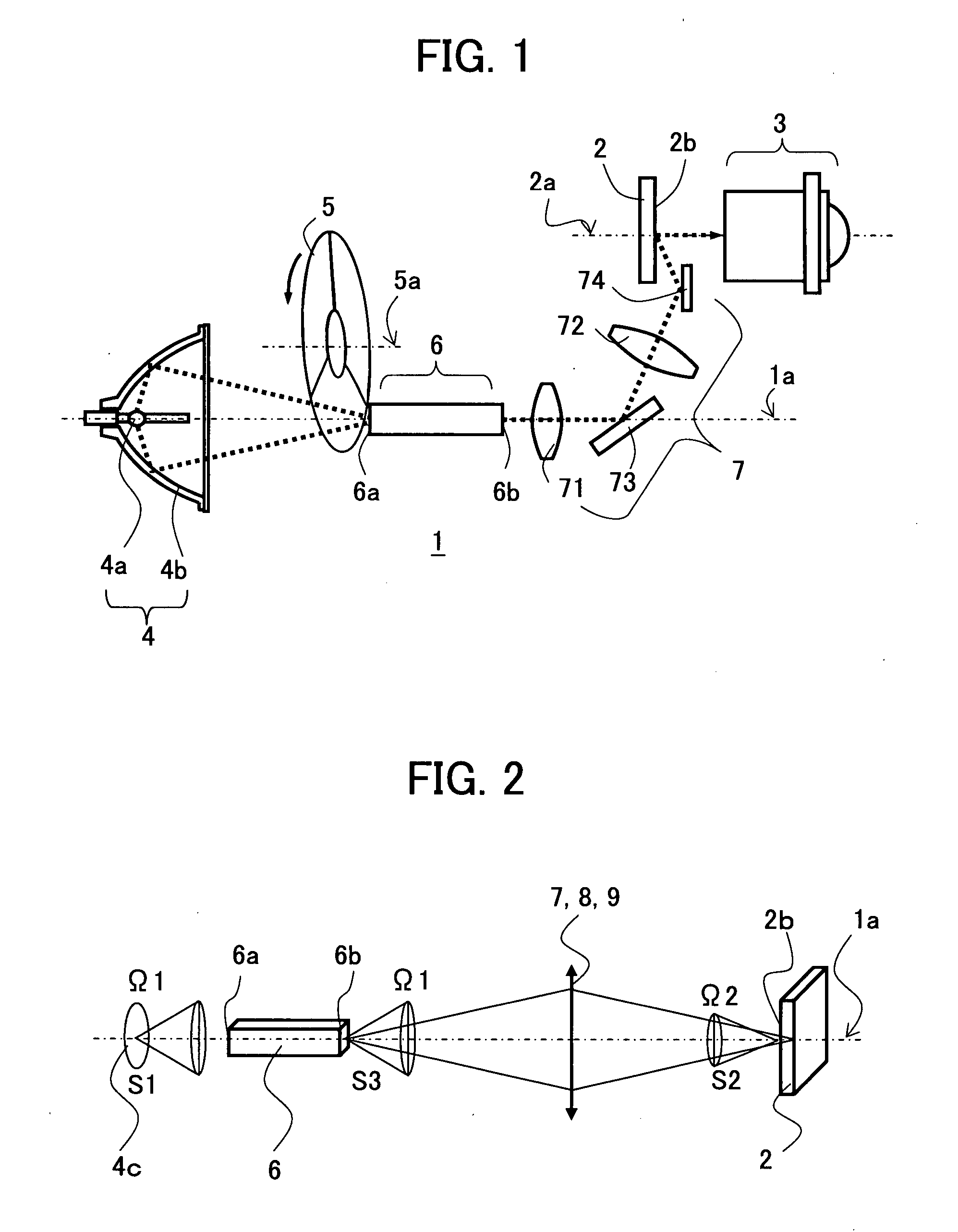
[0027]FIG. 1 is a diagram schematically showing a configuration of an optical system of a projection display apparatus according to the first embodiment of the present invention.

[0028]As shown in FIG. 1, the projection display apparatus according to the first embodiment includes an illumination optical system 1, a DMD element 2 as a reflective light valve, and a projecting optical system 3 for projecting an image, which is formed on a surface to be illuminated (i.e., an image forming area) 2b of the DMD element 2 illuminated by the illumination optical system 1, onto a screen (not shown). The illumination optical system 1 is an optical system for projecting light onto the surface to be illuminated 2b of the DMD element 2. The illumination optical system 1 includes a light source lamp unit 4, a rotary color filter 5 that transmits light of a specified wavelength band of light emitted from the light source lamp unit 4, a light intensity equalizing element 6 which equalizes an intensit...

second embodiment

[0064]FIG. 14 is a diagram schematically showing a configuration of an optical system of a projection display apparatus according to the second embodiment of the present invention.

[0065]In FIG. 14, the constituent elements that are the same as or correspond to those in FIG. 1 (first embodiment) are assigned the same reference numerals or symbols. As shown in FIG. 14, the projection display apparatus according to the second embodiment is different from that according to the first embodiment in that the light source lamp unit 4 and the color filter 5 in the first embodiment is replaced by a laser light source optical system 8 using a laser light source. Except for this point, the projection display apparatus according to the second embodiment is the same as that according to the first embodiment.

[0066]As shown in FIG. 14, the laser light source optical system 8 includes a plurality of colors (three colors, in FIG. 14) of laser light sources 81, a plurality of (three, in FIG. 14) light...


PUM


Abstract

A projection display apparatus includes a light source, a light intensity equalizing element, a reflective light valve, a relay optical system, and a projecting optical system; the light intensity equalizing element being an optical device in which a cross-sectional shape in a direction orthogonal to a central axis of the light has four corners; the cross-sectional shape of the light intensity equalizing element being determined in accordance with a rectangular ideal illumination area determined so as to include the image forming area on the reflective light valve, an illumination area on the reflective light valve when a reference light intensity equalizing element is assumed to be used, the reference light intensity equalizing element being rectangular in a cross-sectional shape in a direction orthogonal to the central light ray, and the cross-sectional shape of the reference light intensity equalizing element.

Description

BACKGROUND OF THE INVENTION[0001]1. Field of the Invention[0002]The present invention relates to a projection display apparatus for projecting an mage onto a screen and, in particular, to a projection display apparatus using a reflective light valve such as a Digital Micromirror Device (hereinafter referred to as “DMD”) and a reflective liquid crystal display device.[0003]2. Description of the Related Art[0004]Some conventional projection display apparatuses employ a construction in which light emitted from a light source is led to a light valve through a light tunnel (i.e., a cylindrical optical device). For example, see paragraph 0034 and FIG. 2 of Japanese Patent Application Kokai (Laid-Open) Publication No. 2004-252112 (Patent Document 1). This light tunnel has a tapered portion formed on an incident side so as to continuously decrease the cross sectional area of the tapered portion and a parallel portion formed on an emitting side so as to make the cross-sectional shape of the ...

Claims


Application Information

Patent Timeline
Patent Type & Authority Applications(United States)
IPC IPC(8): G03B21/28
CPCG02B27/0994H04N9/3129H04N9/3152G03B21/2046Y10S385/901G03B33/08G03B21/208
Inventor KOJIMA, KUNIKOSASAGAWA, TOMOHIRO
Owner MITSUBISHI ELECTRIC CORP
Why Eureka
Try Eureka