Tolerance ring for data storage with cut-out feature for mass control

a technology of tolerance rings and data storage, applied in the field of tolerance rings, can solve problems such as data loss, tribological failure of the interface, damage to the disk and head, etc., and achieve the effects of reducing the eccentricity of the mass of the actuator arm assembly, reducing the eccentricity of the mass, and maximizing flexibility

Active Publication Date: 2008-02-28
INTRL PLEX TECH INC
View PDF56 Cites 11 Cited by
  • Summary
  • Abstract
  • Description
  • Claims
  • Application Information

AI Technical Summary

Benefits of technology

[0017]A tolerance ring configured to improve mass eccentricity of an actuator arm assembly. The tolerance ring has a cylinder with a predetermined length between two ends, with a gap along the predetermined length of the cylinder, the gap having a first and a second edge, the cylinder having an aperture in the surface of the cylinder at the second edge. In one embodiment, the tolerance ring has a first tab protruding from the first edge of the gap and coupling to the cylinder at the second edge of the gap. Combining the aperture with tabs allows maximum flexibility in reducing mass eccentricity. The first tab is engageable with the aperture in the surface of the cylinder. The first tab configuration may be L-shaped or U-shaped. The aperture may be placed as required, enclosing along an edge of the gap to reduce mass imbalance and improve mass eccentricity of the tolerance ring. In another embodiment, the tolerance ring has a second tab protruding from the second edge of the gap, the second tab coupling to the first tab on the first edge. The first and second tabs are adapted to hook together and close the gap.

Problems solved by technology

Because there is relative motion between the disk surface and the magnetic head due to the disk rotation and head actuation, continuous contact between the head and disk can lead to tribological failure of the interface.
Such tribological failure, known colloquially as a “head crash,” can damage the disk and head, and usually cause data loss.
For example, the gap or spacing between the ends in prior art tolerance rings can cause mass eccentricity thereby affecting the dynamic balance of the actuator.
Furthermore, minimizing the gap helps reduce mass imbalance but the tolerance ring ends are still rather long due to manufacturing constraints.

Method used


Image

  • Tolerance ring for data storage with cut-out feature for mass control
  • Tolerance ring for data storage with cut-out feature for mass control
  • Tolerance ring for data storage with cut-out feature for mass control

Examples


Embodiment Construction

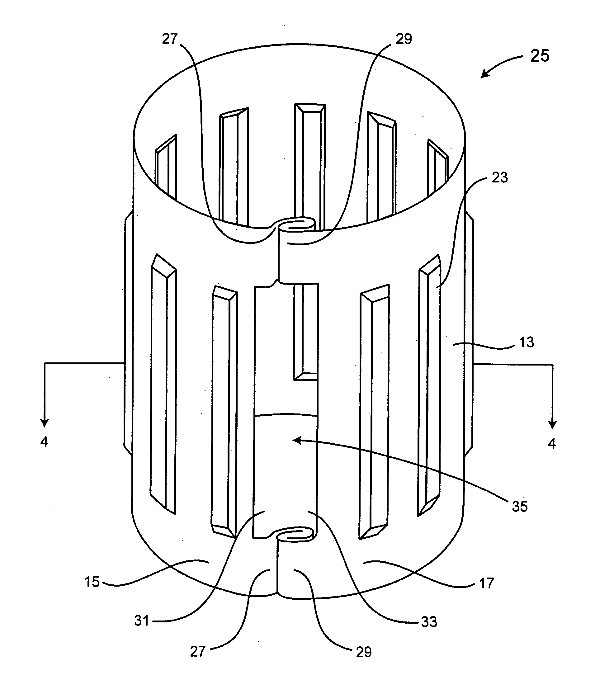
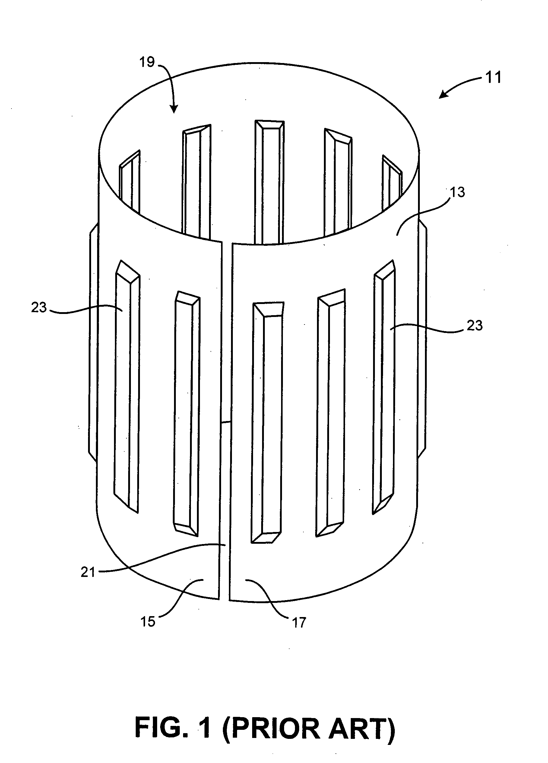
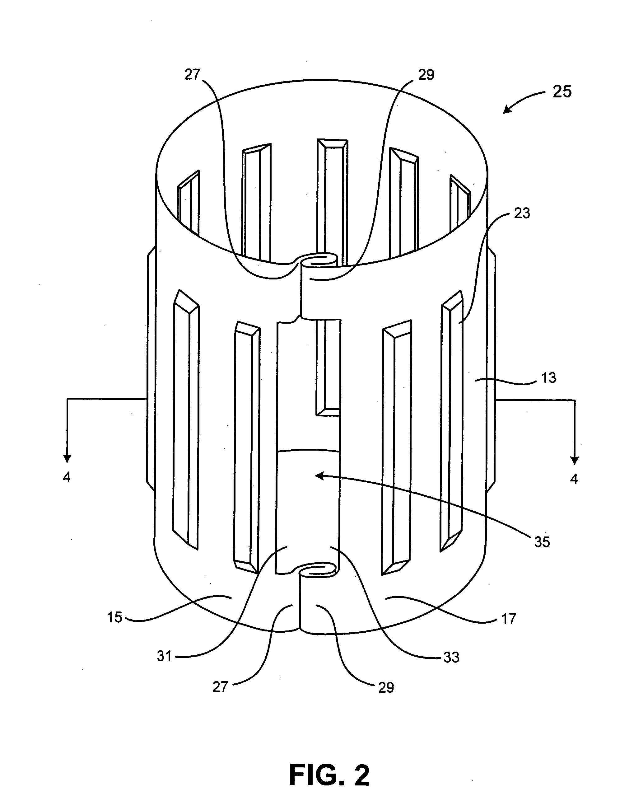
[0031]FIG. 1 illustrates a perspective view of a prior art tolerance ring design 11. In one embodiment, the tolerance ring 11 is made from 300 Series stainless steel. The tolerance ring 11 is formed from a substantially planar base portion that is curved to form a cylinder 13. The cylinder 13 has a first radius about a central axis and extends for a fixed length parallel to the central axis. Radial expansion and contraction of cylindrical opening 19 is facilitated by a gap 21 along the length of tolerance ring 11, the gap 21 having a first edge 15 and a second edge 17. 100301 The tolerance ring 11 has a plurality of contacting portions 23. The contacting portions 23 generally have a rhomboidal cross-sectional shape extending axially along the cylinder 13. As shown in FIG. 1, the contacting portions 23 project radially outward in a direction away from the interior of the tolerance ring 11. It is recognized that alternative configurations known in the art include tolerance rings with ...


PUM

PropertyMeasurementUnit
lengthaaaaaaaaaa
radial distanceaaaaaaaaaa
mass imbalanceaaaaaaaaaa

Abstract

A tolerance ring configured to improve mass eccentricity of an actuator arm assembly. The tolerance ring has a cylinder with a predetermined length between two ends, with a gap along the predetermined length of the cylinder, the gap having a first and a second edge, the cylinder having an aperture in the surface of the cylinder at the second edge.

Description

BACKGROUND OF THE INVENTION[0001]1. Field of the Invention[0002]This invention relates generally to bearing tolerance rings. More particularly, the invention pertains to tolerance rings used in cartridge bearings for actuator arms in information storage devices, such as hard disk drives.[0003]2. Description of Related Art[0004]A key component of any computer system is a device to store data. One common place for storing massive amounts of data in a computer system is on a disc drive. The most basic parts of a disc drive are a disc that is rotated, an actuator that moves a transducer to various locations on the disc, and electrical circuitry that is used to write and read data to and from the disc. Coupled to the actuator is a head-gimbal assembly (HGA) that includes a head and metal suspension. The HGA's can be stacked together into a head-stack assembly (HSA), which is propelled across the disk surface by the actuator. There are a variety of disc drives in use today, such as hard d...

Claims


Application Information

Patent Timeline
Patent Type & Authority Applications(United States)
IPC IPC(8): G11B5/54
CPCG11B5/4813Y10T403/7047F16C11/04F16C27/00F16C2370/12F16D1/0835
Inventor HANRAHAN, KEVIN P.SCHMIDT, RYAN J.DEXTER, DAVID D.
Owner INTRL PLEX TECH INC
Why Eureka
Try Eureka