Synchronous rectifying forward converter

a forward converter and synchronous technology, applied in the field of forward converters, can solve the problems of inability to absorb reverse current from the output side, unstable circuit operation, etc., and achieve the effect of preventing self-excited oscillation, and reducing the number of components

Active Publication Date: 2008-02-28
MURATA MFG CO LTD
View PDF7 Cites 17 Cited by
  • Summary
  • Abstract
  • Description
  • Claims
  • Application Information

AI Technical Summary

Benefits of technology

[0024] [4] In order to drive the commutating switch element (Q3), the commutating switch element control circuit (31) to control the voltage of the control terminal of the commutating switch element (Q3) on the basis of an ON / OFF control signal of the rectifying switch element (Q2) is provided. Accordingly, both the rectifying switch element (Q2) and the commutating switch element (Q3) are forcefully turned ON / OFF in synchronization with the main switch element (Q1), so that self-excited oscillation is prevented.
[0025] [5] The first pulse transformer (T2) to transmit ON timing as a trigger pulse in the drive signal of the main switch element (Q1) output from the switching control circuit (23) from the primary side to the secondary side; and the second pulse transformer (T3) to transmit OFF timing as a trigger pulse from the primary side to the secondary side are provided. Accordingly, the circuit connected to the primary side and the secondary side of the pulse transformers (T2 and T3) is not complicated, and thus an ON timing signal and an OFF timing signal can be reliably separated.
[0026] [6] The diode bridge to output an ON timing signal and an OFF timing signal of the main switch element (Q1) is provided on the secondary side of the pulse transformer (T2) of the synchronous rectifier element driving circuit (24). Accordingly, ON timing and OFF timing of the main switch element (Q1) can be transmitted from the primary side to the secondary side by using a single pulse transformer, and thus the number of components can be reduced.
[0027] [7] The synchronous rectifier element driving circuit (24) includes the flip-flop (34) of which state is switched at ON and OFF of the main switch element (Q1), the flip-flop controlling the rectifying switch element (Q2) or the commutating switch element (Q3) by using the state signal. Accordingly, the number of components can be easily reduced by using the integrated flip-flop.

Problems solved by technology

However, in the synchronous rectifying forward converter of so-called indirect control type shown in FIG. 1, which controls the synchronous rectifier elements 5 and 6 by using a winding voltage of the transformer, the following problem occurs.
Furthermore, the circuit operation becomes unstable due to excitation of the choke coil 8 and the ON-period of the synchronous rectifier elements 5 and 6 is not controlled, so that disadvantageously a reverse current from the output side cannot be absorbed.

Method used


Image

  • Synchronous rectifying forward converter
  • Synchronous rectifying forward converter
  • Synchronous rectifying forward converter

Examples


first embodiment

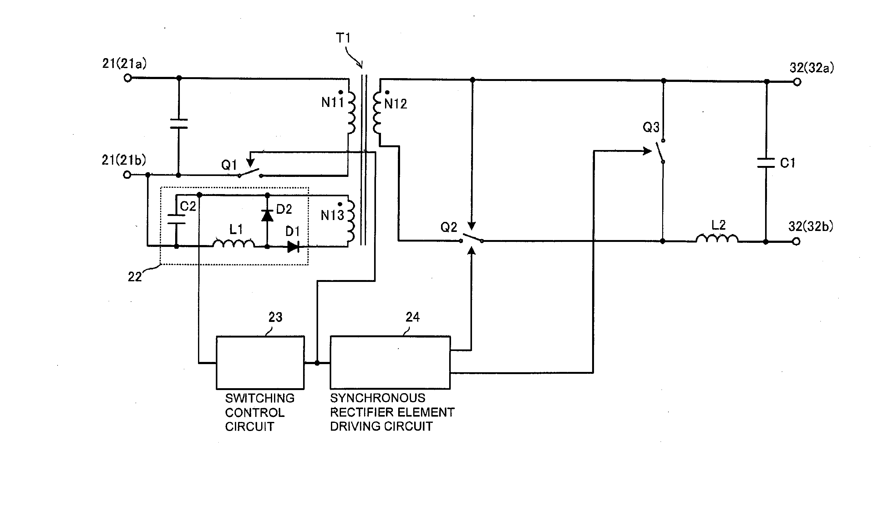
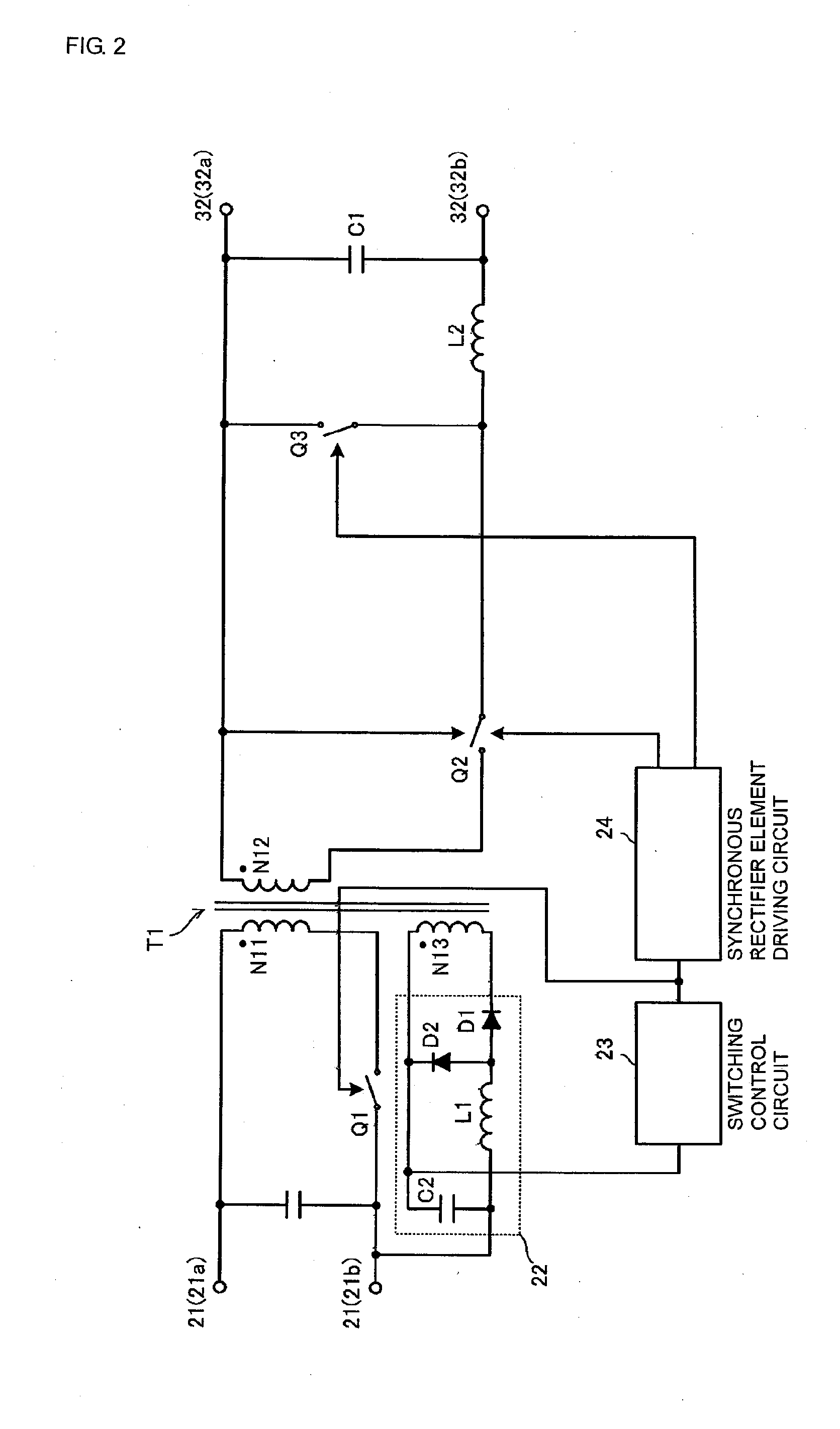
[0069] A configuration of a synchronous rectifying forward converter according to a first embodiment is described with reference to FIG. 2.

[0070]FIG. 2 is a circuit diagram of the synchronous rectifying forward converter. Part of this figure is illustrated with blocks and symbols. As shown in FIG. 2, a main transformer T1 includes a primary winding N11, a secondary winding N12, and a tertiary winding N13. The primary winding N11 connects in series to a main switch element Q1, and a capacitor is connected between input terminals 21 (21a and 21b). The secondary winding N12 of the main transformer T1 connects in series to a choke coil L2 and a rectifying switch element Q2, and a smoothing capacitor C1 is connected between output terminals 32 (32a and 32b). Also, a commutating switch element Q3 forms a loop together with the choke coil L2 and the smoothing capacitor C1 and is placed at a position in a commutating path during release of excitation energy of the choke coil L2.

[0071] The...

second embodiment

[0118] Hereinafter, a configuration of a synchronous rectifying forward converter according to a second embodiment is described with reference to FIGS. 4 to 6.

[0119]FIG. 4 is a circuit diagram of the synchronous rectifying forward converter according to the second embodiment, and FIGS. 5 and 6 are waveform diagrams of a main part thereof.

[0120] As shown in FIG. 4, the switching control circuit 23 operates by using an output from the tertiary rectifying and smoothing circuit 22 as power and includes a switching controlling IC 230 to receive divided voltage from resistors R2 and R3 of the same output. The switching controlling IC 230 outputs switching control signals to the gate of the main switch element Q1 via primary windings N21 and N31 of pulse transformers T2 and t3. At that time, the switching controlling IC 230 performs PWM control on the main switch element Q1 so that the above-described divided voltage match a reference voltage on the basis of the received divided voltage ...

third embodiment

[0134] Hereinafter, a configuration of a synchronous rectifying forward converter according to a third embodiment is described with reference to FIGS. 7 and 8.

[0135]FIG. 7 is a circuit diagram of the synchronous rectifying forward converter according to the third embodiment, and FIG. 8 is a waveform diagram of a main part thereof.

[0136] In the third embodiment, the gate of the rectifying switch element Q2 connects to one end of the secondary winding N12 of the main transformer T1, and the rectifying switch element Q2 is controlled with the voltage of the transformer as in a known art. On the other hand, the output voltage of the control voltage signal generating circuit 26 is applied between the gate and source of the commutating switch element Q3 via the controlling switch element Q7. The controlling switch element Q6 is connected between the gate of the controlling switch element Q7 and the ground. Also, the commutating switch controlling switch element Q4 is connected between t...


PUM


Abstract

A first drive control signal regenerating circuit outputs an ON timing drive signal at turn-ON of a main switch element, and a second drive control signal regenerating circuit generates an OFF timing drive signal at turn-OFF of the main switch element. A rectifying switch controlling switch element connected between the gate and source of a rectifying switch element is driven by an output of the second drive control signal regenerating circuit. An output of the first drive control signal regenerating circuit connects to the gate of a commutating switch controlling switch element, which connects to one end of an auxiliary winding, the other end thereof being connected to the gate of a commutating switch element. Accordingly, the rectifying switch element is directly controlled from the primary side.

Description

CROSS-REFERENCE TO RELATED APPLICATIONS [0001] This is a continuation under 35 U.S.C. §111(a) of PCT / JP2006 / 317626 filed Sep. 6, 2006, and claims priority of JP2005-304763 filed Oct. 19, 2005, incorporated by reference.BACKGROUND OF THE INVENTION [0002] 1. Technical Field [0003] The present invention relates to a forward converter to synchronously rectify an output current. [0004] 2. Background Art [0005] A conventional synchronous rectifying forward converter is disclosed in Patent Document 1 (Japanese Unexamined Patent Application Publication No. 2000-262051). FIG. 1 shows the circuit of the converter according to Patent Document 1. [0006] In the circuit shown in FIG. 1, after a main switch element 2 on the primary side of a transformer 4 is turned ON, a voltage generated at a secondary winding 4b of the transformer 4 causes a rectifying-side synchronous rectifier element 5 on the secondary side to be turned ON and a commutating-side synchronous rectifier element 6 to be turned OF...

Claims


Application Information

Patent Timeline
Patent Type & Authority Applications(United States)
IPC IPC(8): H02M3/335
CPCY02B70/1475H02M3/33592Y02B70/10
Inventor MOROMIZATO, EITOMATSUMOTO, TADAHIKO
Owner MURATA MFG CO LTD
Why Eureka
Try Eureka