Method and apparatus for photonic resiliency of a packet switched network

a packet switched network and photonic resiliency technology, applied in the field of communication networks, can solve the problems of inability to guarantee the restoration time of the network faster than 50 ms, inconvenient use of bandwidth, and inability to cost-effectively deliver the services of traditional circuit-switched networks

Inactive Publication Date: 2008-02-28
KOLEY BIKASH
View PDF14 Cites 28 Cited by
  • Summary
  • Abstract
  • Description
  • Claims
  • Application Information

AI Technical Summary

Benefits of technology

[0009] (BK. This deleted paragraph seems to

Problems solved by technology

As metro and access area networks constantly evolve to support new packet-based services such as voice-over-internet-protocol and IP-television, traditional circuit-switched networks are not suitable to cost-effectively deliver these services any more.
This leads to a very inefficient use of bandwidth while carrying asynchronous packet based traffic.
Also, due to the signaling time limitations, SONET cannot guarantee faster than 50-ms restoration time.
However, Ethernet switches will not work properly if there is a ring or loop in the topology.
These techniques are slow and cannot provide automati

Method used


Image

  • Method and apparatus for photonic resiliency of a packet switched network
  • Method and apparatus for photonic resiliency of a packet switched network
  • Method and apparatus for photonic resiliency of a packet switched network

Examples


Embodiment Construction

[0027] The present invention will now be disclosed more fully with reference to the accompanying drawings, in order to disclose selected embodiments. This invention may, however, be embodied in many different forms and should not be construed as limited to the embodiment set forth herein. It will also be understood by those skilled in the art that the present invention may be practiced with only some or all aspects of the present invention. For the purpose of a thorough understanding and explanation, the selected embodiments are disclosed herein with the help of specific numbers, materials and configurations. However, it will also be apparent to those skilled in the art that the present invention may be practiced without these specific details.

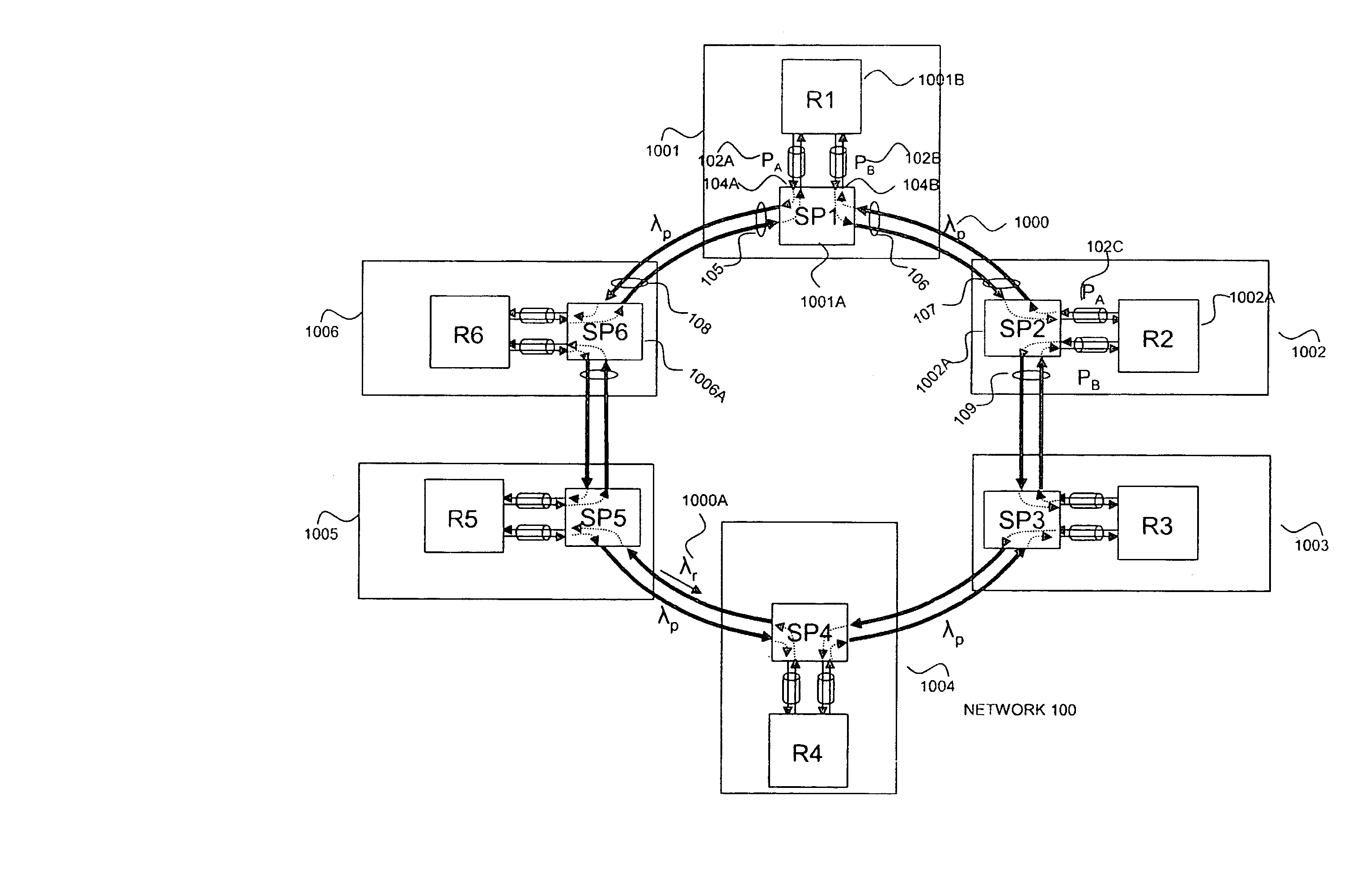
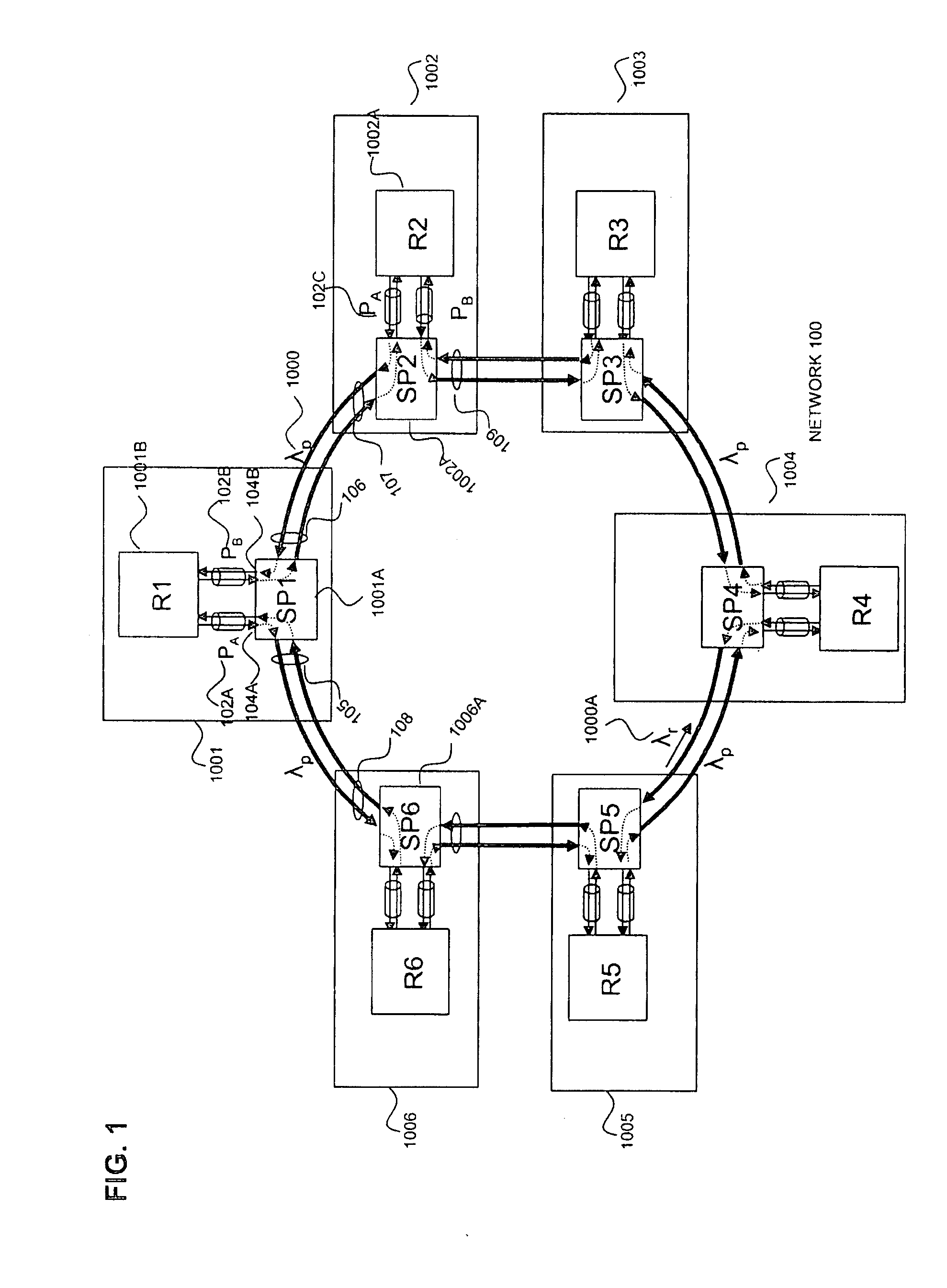
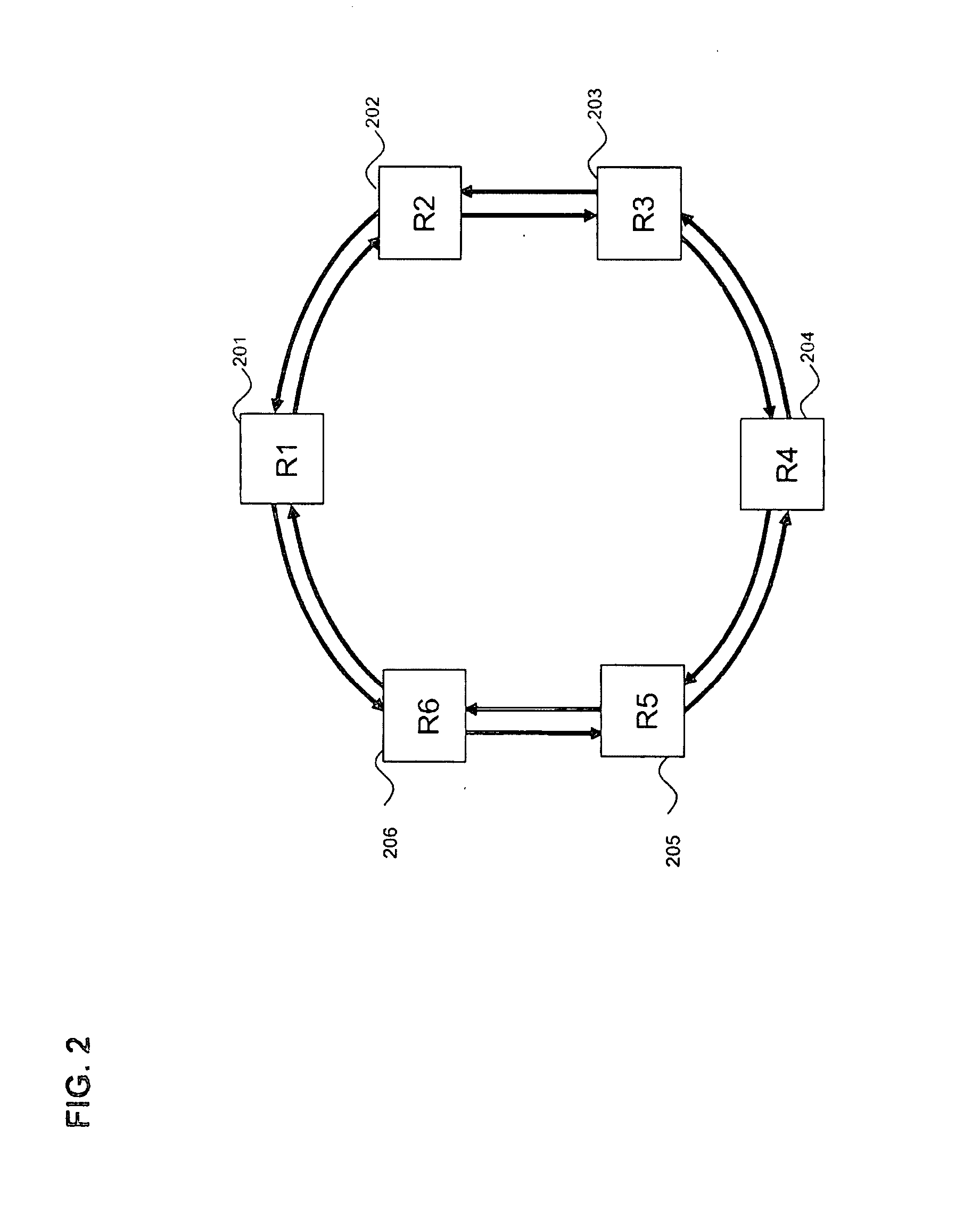
[0028] As is understood by those skilled in the art, communication networks are often described in reference to a network layer model such as one specified by the International Standards Organization (ISO) in the Open System Interface (OSI) r...


PUM


Abstract

A resilient photonic network includes a plurality of resilient switching nodes, each node comprising a photonic switch and one of a Layer-2/3 switch and router, and a plurality of bi-directional ports, each connected between the photonic switch the one of a Layer-2/3 switch and router, wherein at least one optical signal having a specific wavelength is transmitted through a first network port of a first one of the plurality of resilient switching nodes to an adjacent second one of the plurality of resilient switching nodes and the at least one optical signal is transmitted through a second network port of the first one of the plurality of resilient switching nodes to an adjacent third one of the plurality of resilient switching nodes to establish a bi-directional connectivity between the first, second, and third pluralities of resilient switching nodes.

Description

[0001] This application claims priority to U.S. Provisional Application 60 / 812,492 filed Jun. 12, 2006 and U.S. Provisional Application 60 / 812,496 filed Jun. 12, 2006. This application incorporates by reference these two provisionals.BACKGROUND OF THE INVENTION [0002] 1. Field of the Invention [0003] The present invention relates generally to communication networks and more specifically to a method and an apparatus for establishing a resilient photonic packet switched network. [0004] 2. Background of the Invention [0005] As metro and access area networks constantly evolve to support new packet-based services such as voice-over-internet-protocol and IP-television, traditional circuit-switched networks are not suitable to cost-effectively deliver these services any more. Traditional Metropolitan Area Networks (MAN) have predominantly been based on the Synchronous Optical NETwork (SONET) technology. SONET based circuit switched networks offer some very desirable network features such a...

Claims


Application Information

Patent Timeline
IPC IPC(8): H04J14/00
CPCH04J14/0201H04J14/0227H04J14/0283H04J14/0294H04J14/0241H04L12/437H04Q11/0062H04Q11/0066H04Q2011/0081H04J14/0295
Inventor KOLEY, BIKASH
Owner KOLEY BIKASH
Why Eureka
Try Eureka