Medical treatment equipment
a technology for medical treatment and equipment, applied in the field of medical treatment equipment, to achieve the effect of ensuring the transmission of rotational torqu
- Summary
- Abstract
- Description
- Claims
- Application Information
AI Technical Summary
Benefits of technology
Problems solved by technology
Method used
Image
Examples
first embodiment
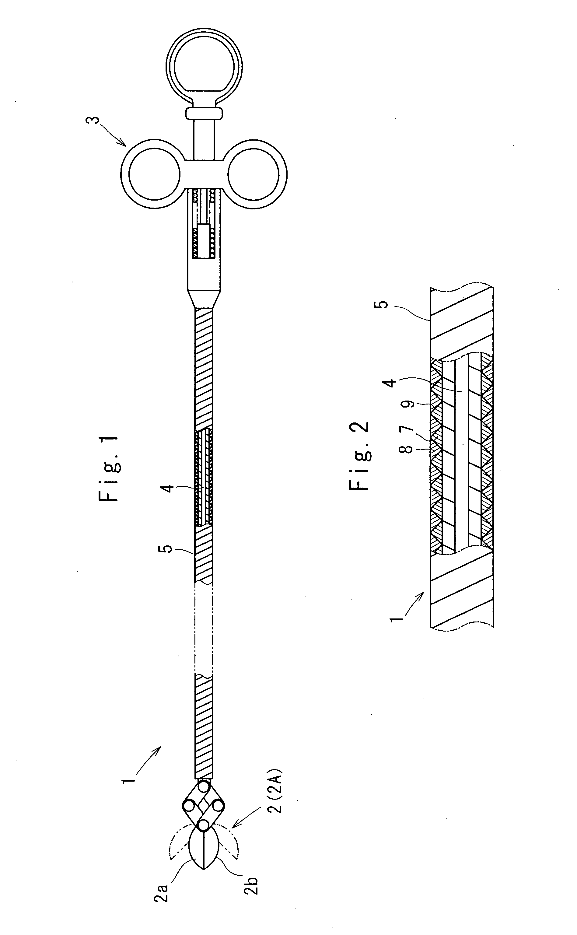
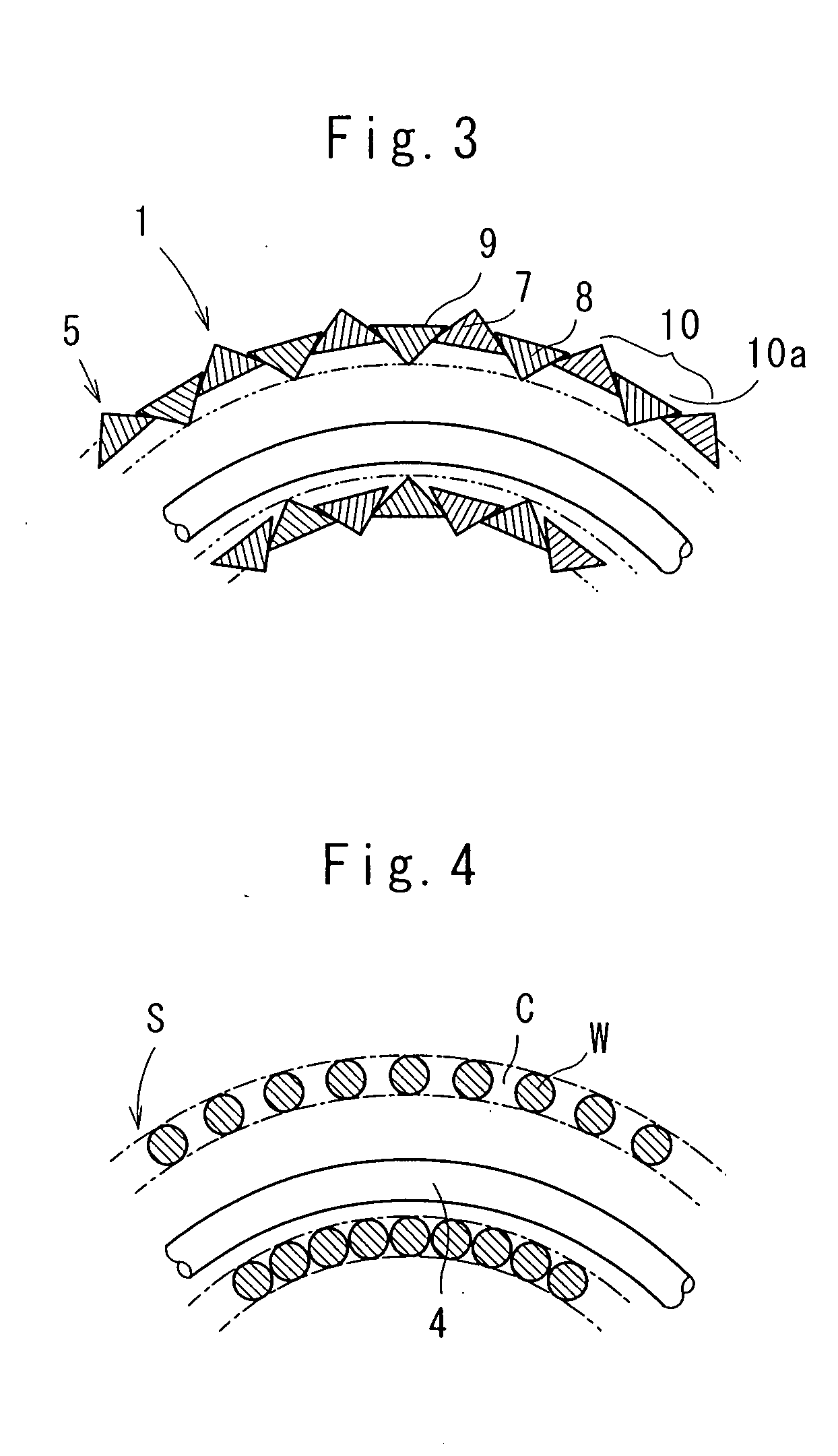
[0067]Referring to FIGS. 1 through 6 which show a medical treatment equipment 1 according to the invention, a distal end portion of the medical treatment equipment 1 has a treatment portion 2, and a proximal end portion of the medical treatment equipment 1 has an operational portion 3. Between the treatment portion 2 and the operational portion 3, there is provided an elongate core 4 which connects the operational portion 3 to the treatment portion 2. A long flexible sheath body 5 is provided to have the elongate core 4 inserted therethrough as shown in FIGS. 1 and 2.
[0068]The medical treatment equipment 1 works as an endoscopic treatment device in which the treatment portion 2 is a biopsy cup 2A provided to open and shut its blades 2a, 2b of scissors by a push-pull manipulation of the elongate core 4 through the operational portion 3. Through the push-pull manipulation of the elongate core 4 by way of the operational portion 3, the elongate core 4 axially moves within the sheath bo...
second embodiment
[0104]FIGS. 7 and 8 show the invention in which the identical cross sectional shapes of the wire elements 7, 8 are equilateral trapezoids with the oblique sides forming 45 degrees against a lower long side.
[0105]Among the cross sectional shapes of the wire elements 7, 8, the wire element 7 makes an upper short side (except for the oblique lateral sides) of the trapezoid face an outer diameter side of the sheath body 5, and the wire element 8 makes the upper short side of the trapezoid face an inner diameter side of the sheath body 5 as shown in FIG. 7.
[0106]In the second embodiment of the invention, the neighboring wire elements 7, 8 make the lateral sides of the trapezoids slide each other at the mutual neighborhood side 9 upon bending the sheath body 5 as shown in FIG. 8.
[0107]The sliding movement between the lateral sides of the trapezoids absorbs both the tensile stresses and the contractile stresses developed on the sheath body 5 due to the bending deformation, thus resultantly...
third embodiment
[0109]FIGS. 9 and 10 show the invention in which the cross sectional shapes of the wire elements 7, 8 are analogous each other so that either one of the wire elements 7, 8 is smaller in scale than the other.
[0110]With the wire elements 7, 8 defined to be at least analogous each other, it is possible for the wire elements 7, 8 to form the tight knit coil structure even if the cross sectional shapes of the wire elements 7, 8 are not necessarily the same. Such is the structure that the sheath body 5 forms the concave-convex portion 10 (concave portion 10a) even in the straight-shaped configuration. This enables the user to clearly delineate the supersonic image under the three-dimensional supersonic echo.
PUM
 Abstract
Description
Claims
Application Information
 - R&D
- Intellectual Property
- Life Sciences
- Materials
- Tech Scout
- Unparalleled Data Quality
- Higher Quality Content
- 60% Fewer Hallucinations
Browse by: Latest US Patents, China's latest patents, Technical Efficacy Thesaurus, Application Domain, Technology Topic, Popular Technical Reports.
© 2025 PatSnap. All rights reserved.Legal|Privacy policy|Modern Slavery Act Transparency Statement|Sitemap|About US| Contact US: help@patsnap.com


