Bifurcation stent delivery catheter and method

a stent and catheter technology, applied in the field of catheters and systems, can solve the problems of stent deployment assembly, which supports and transports the stent in a collapsed state, and is not rotatably controlled, and the stent is delivered and deployed relative to the side branch extremely difficult,

Inactive Publication Date: 2008-02-28
ABBOTT CARDIOVASCULAR
View PDF15 Cites 80 Cited by
  • Summary
  • Abstract
  • Description
  • Claims
  • Application Information

AI Technical Summary

Problems solved by technology

While these bifurcation stent designs have encountered varying degrees of success, one major problem associated with all bifurcation systems is that the delivery and deployment of the stent, relative to the side branch, is extremely difficult.
This is due primarily to the difficulty in properly controlling the orientation, alignment and position of the stent deployment assembly relative to the main branch and side branch of the bifurcated vessel.
During advancement of the catheter shaft along the predisposed guidewire, the stent deployment assembly, which supports and transports the stent in a collapsed state, is not rotatably controlled.
Transmitting a controlled rotation to the distal end of the catheter over the length of the flexible catheter shaft, however, is nearly impossible.
Due in part to the complex anatomy of a coronary artery, the flexible catheter shaft will not adequately transfer torque to the dilatory.
Although a proximal portion of the delivery catheter, which often includes a relatively rigid material such as a hypotube or a polymeric tube with a stiffening wire, can reasonably transmit torque, the more distal portions of the flexible catheter shaft cannot.

Method used


Image

  • Bifurcation stent delivery catheter and method
  • Bifurcation stent delivery catheter and method
  • Bifurcation stent delivery catheter and method

Examples


Embodiment Construction

[0070] While the present invention will be described with reference to a few embodiments, the description is illustrative of the invention and is not to be construed as limiting the invention. Various modifications to the present invention can be made to the preferred embodiments by those skilled in the art without departing from the scope of the invention as defined by the appended claims. It will be noted here that for a better understanding, like components are designated by like reference numerals in the various figures.

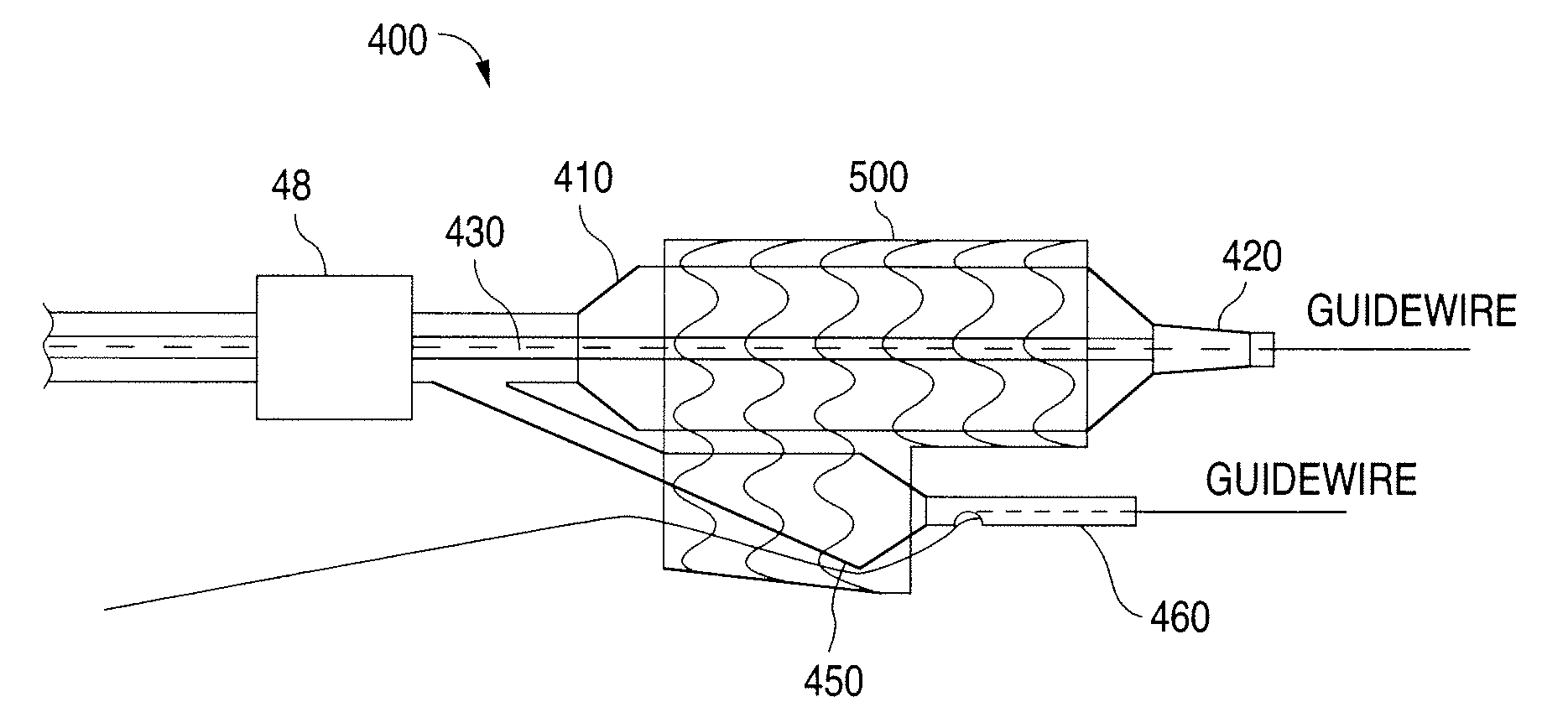
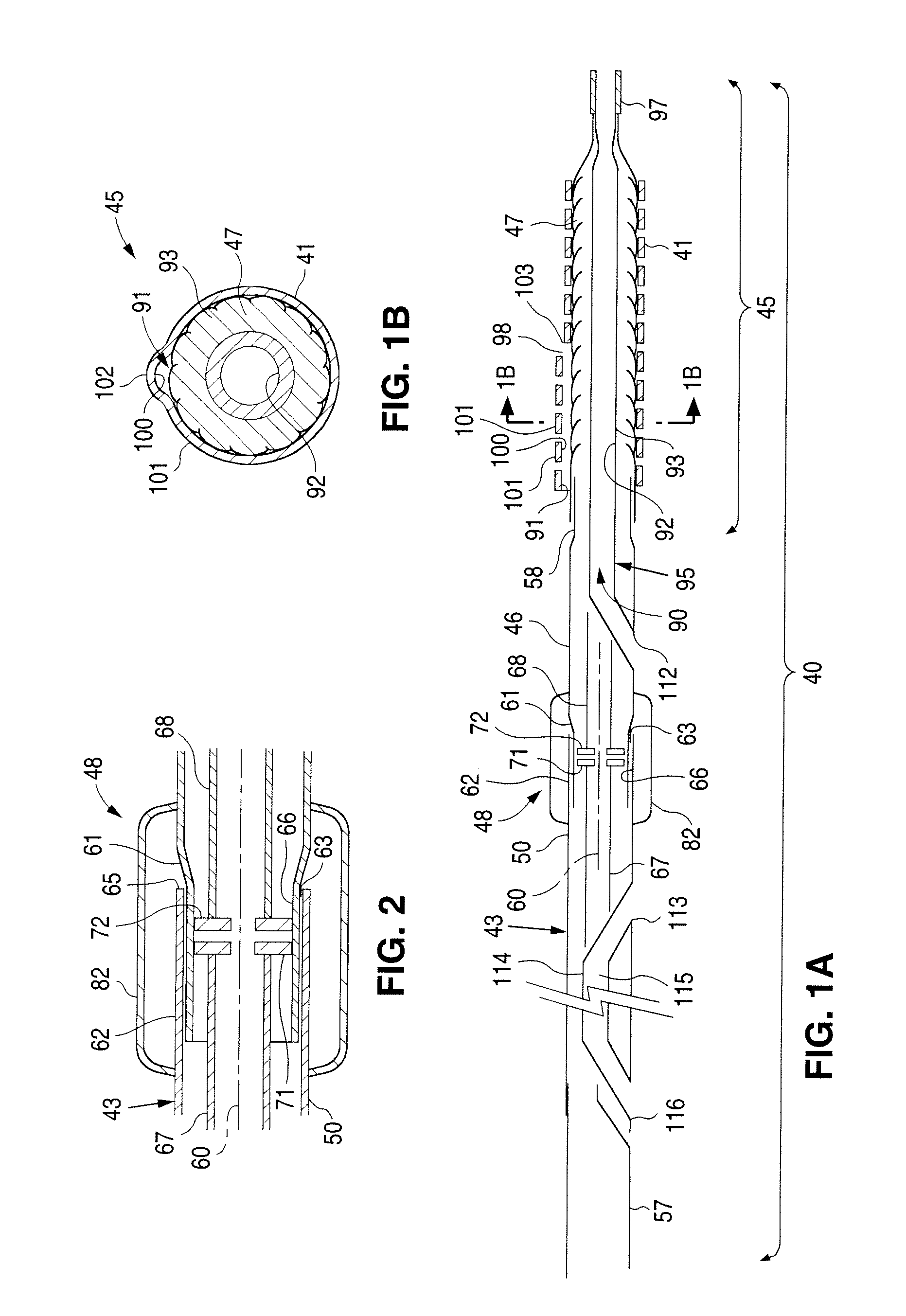
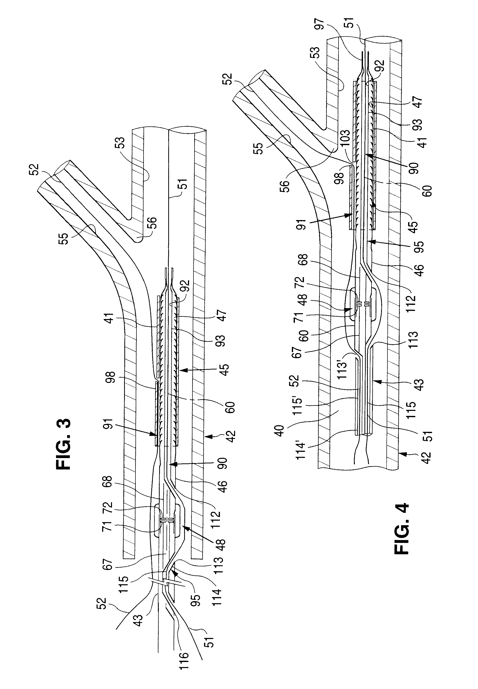
[0071] Referring now to FIGS. 1-5, a stent delivery system, generally designated 40, is described. The system 10 delivers and deploys a radially expandable stent 41 (e.g., a bifurcation stent) at a strategic orientation and location in a body vessel 42 (FIGS. 3 and 4). The delivery system 40 includes an elongated shaft 43 sized suitably for insertion into the body vessel 42. A stent deployment assembly 45 includes a tubular distal transition portion 46 supportin...


PUM


Abstract

A bifurcation stent delivery catheter includes a first branch balloon, a second branch balloon adjacent the first branch. A centering balloon is optionally disposed distal of the second branch balloon. The balloons are coupled by a coupling device to a main shaft of a catheter. The coupling device allows axial forces to be transmitted from the main shaft to the balloons while allowing the balloons to rotate axially relative to the main shaft with ease. The coupling device functions as an axial rotational joint. The coupling device can have a flexible tubular member that connects the balloons to the main shaft, the tubular member having a torsional flexibility greater than that of the main shaft. The coupling device can have a tubular wall having a cut extending circumferentially around the tubular wall and protective boot covering the cut. The coupling device can have a wound member that allows the axial rotation.

Description

[0001] This application claims the benefit of U.S. Provisional Application No. 60 / 822,898, filed Aug. 18, 2006, the entire disclosure of which is hereby incorporated by reference.FIELD OF THE INVENTION [0002] The present invention relates generally to catheters and systems and methods used for delivering devices such as, but not limited to, intravascular stents and therapeutic agents to sites within vascular or tubular channel systems of the body. More particularly, the present invention relates to delivery catheters and systems and methods for delivering stents to bifurcated vessels. BACKGROUND OF THE INVENTION [0003] A type of endoprosthesis device, commonly referred to as a stent, may be placed or implanted within a vein, artery or other tubular body organ for treating occlusions, stenoses, aneurysms or dissections of a vessel by reinforcing the wall of the vessel or by expanding the vessel. Stents are normally placed to scaffold the vessel and avoid elastic recoil after angiopla...

Claims


Application Information

Patent Timeline
Patent Type & Authority Applications(United States)
IPC IPC(8): A61M25/10
CPCA61F2/856A61F2220/0025A61F2002/30329A61F2/954
Inventor VON OEPEN, RANDOLFCOFFEY, LORCAN JAMESRIETH, THOMAS MICHAELNEWHAUSER, RICHARD ROYYRIBARREN, TRAVIS RICHARDWILSON, BRUCE
Owner ABBOTT CARDIOVASCULAR
Why Eureka
Try Eureka