
Vacuum Cleaner

a vacuum cleaner and vacuum technology, applied in the field of vacuum cleaners, can solve the problems of dust generation, lower dust collection efficiency of the dust collecting unit, inconvenience for users, etc., and achieve the effect of convenient use and efficient use of the vacuum cleaner

Active Publication Date: 2008-03-06
LG ELECTRONICS INC
View PDF2 Cites 48 Cited by
  • Summary
  • Abstract
  • Description
  • Claims
  • Application Information

AI Technical Summary

Benefits of technology

The vacuum cleaner described in this patent has several technical effects. First, it increases the density of collected foreign substances by compressing them at a specific position in the dust collecting unit. Second, it prevents dust from being generated when removing the collected foreign substances. Third, it allows for easier and more frequent removal of the collected foreign substances. Fourth, it is designed to be convenient for users, as the compressing operation is simple and can be performed easily. Overall, this vacuum cleaner improves the user experience and makes it more efficient in collecting and removing foreign substances.

Problems solved by technology

This low density of the accumulated foreign substances causes the following problems.
Since the limited space of a dust collection container of the dust collecting unit is easily filled up by the loosely accumulated foreign substances, the dust collection container should be emptied frequently, thereby causing inconvenience to users.
If the dust collection container is not emptied periodically, the build up of the foreign substances disturbs the airflow and thereby lowers the collecting efficiency of the dust collecting unit.
Further, dust generates from the loosely accumulated foreign substances during the cleaning of the dust collection container.
This causes health-related problems and makes the cleaning of the dust collection container more difficult.
Furthermore, when the collected foreign substances are spread throughout the dust collection container, the outer appearance becomes bad to give an unpleasant feeling to the user.

Method used


Image

  • Vacuum Cleaner
  • Vacuum Cleaner
  • Vacuum Cleaner

Examples


Embodiment Construction

[0027] Reference will now be made in detail to the preferred embodiments of the present invention, examples of which are illustrated in the accompanying drawings.

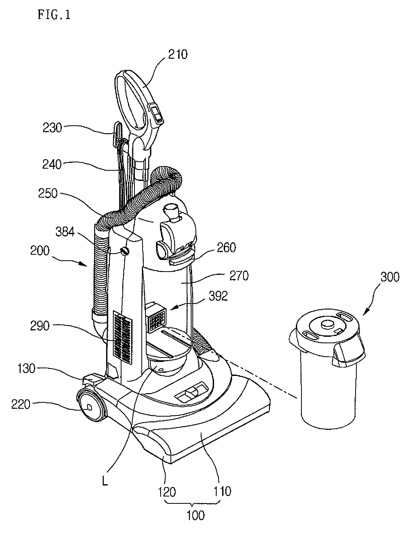
[0028]FIG. 1 is a perspective view of an upright vacuum cleaner according to the present embodiment.

[0029] Referring to FIG. 1, the upright type vacuum cleaner includes a suction nozzle unit 100 sucking air containing foreign substances such as dust and dirt, a main body 200 in which suction power generating unit is installed to suck the air, and an operating unit 210 mounted on a top of the main body 200 so that a user grasps the operating unit 210 in use.

[0030] Hereinafter, the structure of the vacuum cleaner will be more fully described.

[0031] The suction nozzle unit 100, which is designed to suck the air, includes a nozzle upper cover 110 and a nozzle lower cover 120 that form the upper and lower outsides of the suction nozzle unit 100, respectively. The lower nozzle cover 120 defines an air intake (not shown) in a ...


PUM

PropertyMeasurementUnit
pressureaaaaaaaaaa
air suctioning forceaaaaaaaaaa
densityaaaaaaaaaa

Abstract

There is provided a vacuum cleaner. The vacuum cleaner includes a dust separation part separating dust contained in air; a dust storing part storing dust separated by the dust separation part; a compression unit dividing the dust separation part and dust storing part, for compressing dust stored in the dust storing part; a motor connection passage communicated with a motor generating a negative pressure; a compression passage communicated with the dust storing part; a dust collection passage communicated with the dust separation part; and a flow passage control unit selectively opening and closing the compression passage and the dust collection passage.

Description

[0001] This application is a Continuation of co-pending application Ser. No. 11 / 297,435 filed on Dec. 9, 2005, the entire contents of which are hereby incorporated by reference and for which priority is claimed under 35 U.S.C. §120.BACKGROUND [0002] 1. Field [0003] This document relates to a vacuum cleaner. [0004] 2. Description of the Related Art [0005] A typical vacuum cleaner includes a suction nozzle unit to suck air containing foreign substances such as dust and dirt while the suction nozzle unit moves along a floor, a main body in which a suction power generating unit is installed to generate air suctioning force through the suction nozzle unit, a dust collecting unit detachably installed to the main body to filter out the foreign substances, and an operating unit mounted on the main body so that a user grasps the operating unit in use. [0006] The dust collecting unit separates foreign substances from the air sucked through the suction nozzle unit. In one type of the dust coll...

Claims


Application Information

Patent Timeline
Patent Type & Authority Applications(United States)
IPC IPC(8): A47L9/10A47L11/24
CPCA47L9/108A47L9/1608A47L9/165B04C5/185A47L9/1666A47L9/1683A47L9/1691A47L9/1658Y10S55/03A47L9/10A47L9/00Y10S15/08
Inventor LEE, JAE HONGKWON, HYUK JOOKIM, SEOG YONGPARK, SANG JUN
Owner LG ELECTRONICS INC
Learn More