Pneumatic tire

Inactive Publication Date: 2008-03-06
TOYO TIRE & RUBBER CO LTD
6 Cites 5 Cited by

AI-Extracted Technical Summary

Problems solved by technology

As a result, the pneumatic tire is provided, wherein driving performance particularly on a road co...

Benefits of technology

[0011]According to the pneumatic tire of the present invention, driving performance on a road covered with shallow snow becomes good since the lateral groove disposed between circumferential grooves has a sufficient depth. And also, since the depth of the lateral groove between the circumferential grooves is shallower than that of the circumferential grooves, deformation caused by anteroposterior force of the block can be prevented properly, and in addition, the groove bottom sipe in the lateral groove reduces stepped wear, since stress acting on an edge line of the block is alleviated when the anteroposterior force is acted on the block. Furthermore, since the length of the circumferential direction of the tire in the land portion sipe provided on the block is long, the block can move easily in the width direction of the tire, and by developing wear progress in an orthogonal direction to stepped wear in the longitudinal direction, stepped wear in the circumferential direction can be reduced. As a result, the pneumatic tire is provided, wherein driving performance particularly on a road covered with shallow snow is good and irregular wear such as toe and heel wear does not occur easily.
[0012]In the pneumatic tire mentioned hereinbefore, it is preferable that the lateral groove disposed between the circumferential grooves has a bend section in a circular arc shape. By providing the bend section in the lateral groove, edge lines of the block can be...

Abstract

A pneumatic tire provided with a tread pattern on which a plurality of blocks are formed with three circumferential grooves which extend along a circumferential direction of the tire and lateral grooves which traverse the circumferential grooves, wherein the lateral groove disposed between the circumferential grooves has a depth that is from 40 to 70% of a depth of the circumferential groove, a groove bottom sipe with both open ends is formed on a groove bottom of the lateral groove, and a land portion sipe, whose length in the circumferential direction of the tire is longer than that in a width direction of the tire, is formed on the block.

Application Domain

Tyre tread bands/patternsNon-skid devices

Technology Topic

Electrical and Electronics engineeringTread

Image

  • Pneumatic tire
  • Pneumatic tire
  • Pneumatic tire

Examples

  • Experimental program(6)

Example

Comparative Example 1
Conventional Tire
[0060]In the tread pattern shown by FIG. 6, the depth of the circumferential groove and the lateral groove were adjusted to 12 mm, and a radial tire having a size of 195/85R16 was produced. Using the tire, evaluation on the above respective performance was conducted. The results are shown in Table 1.

Example

Comparative Example 2
Conventional Tire
[0061]In the tread pattern shown by FIG. 7, the depth of the circumferential groove and the lateral groove were adjusted to 12 mm, and a radial tire having a size of 195/85R16 was produced. Using the tire, evaluation on the above respective performance was conducted. The results are shown in Table 1.

Example

Example 1
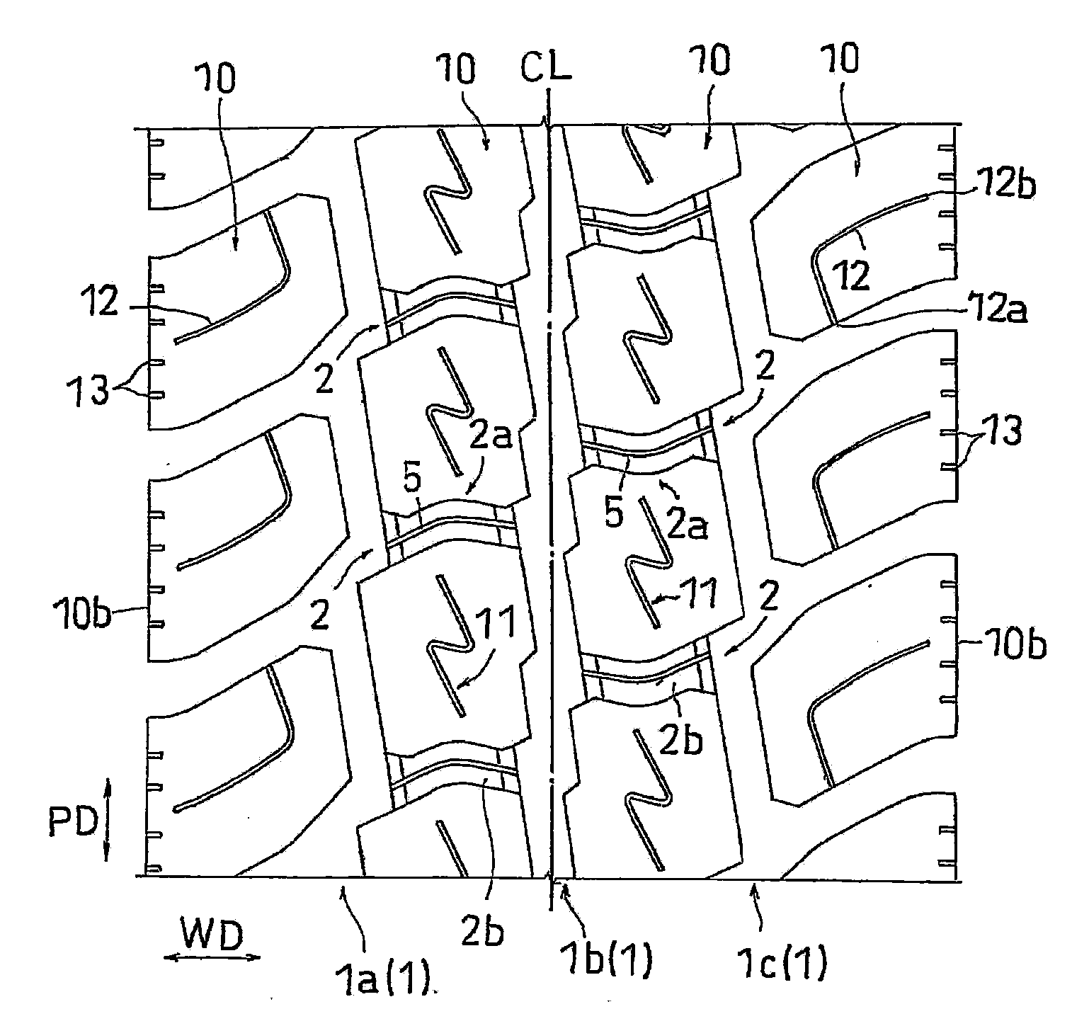
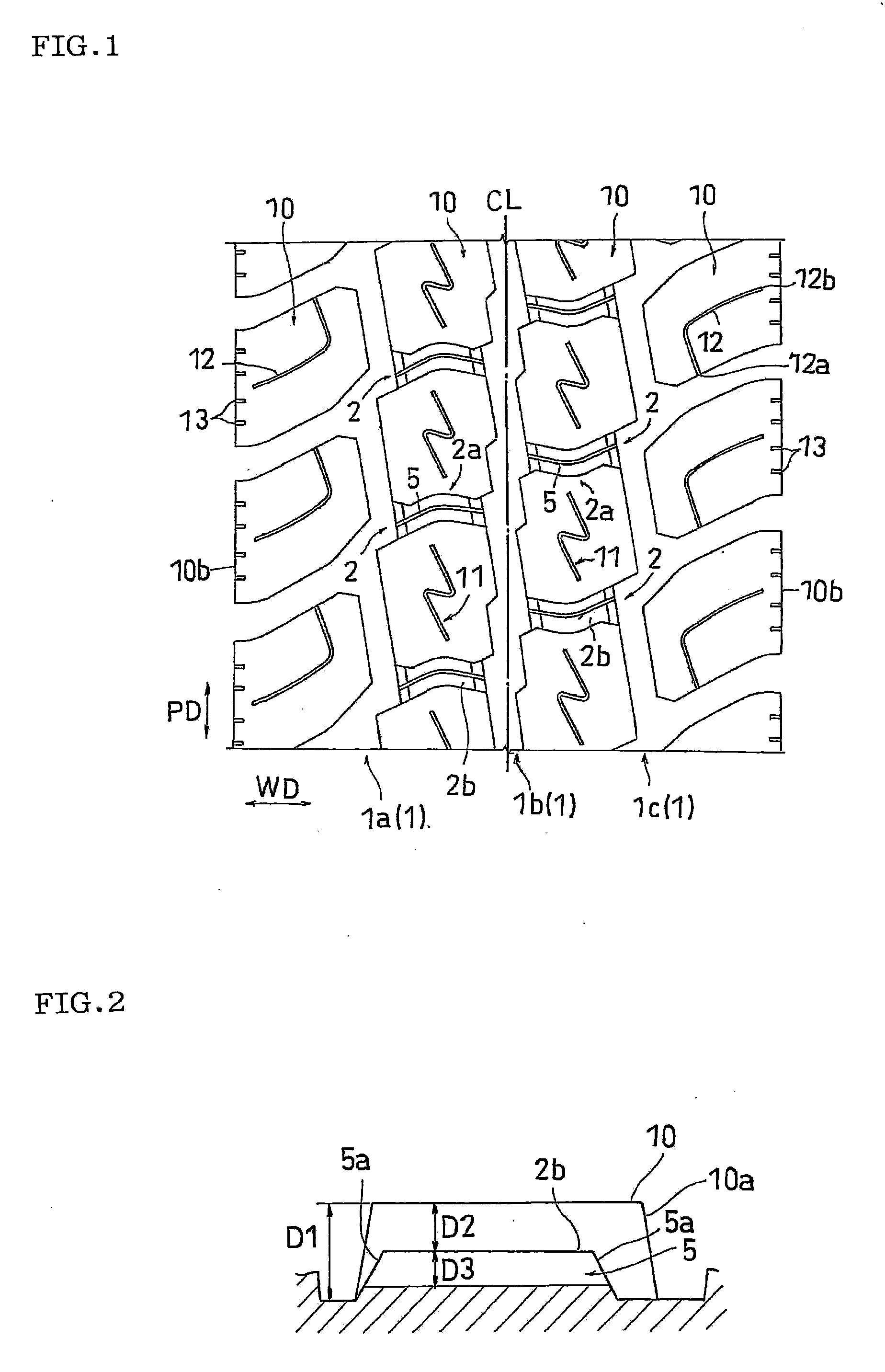
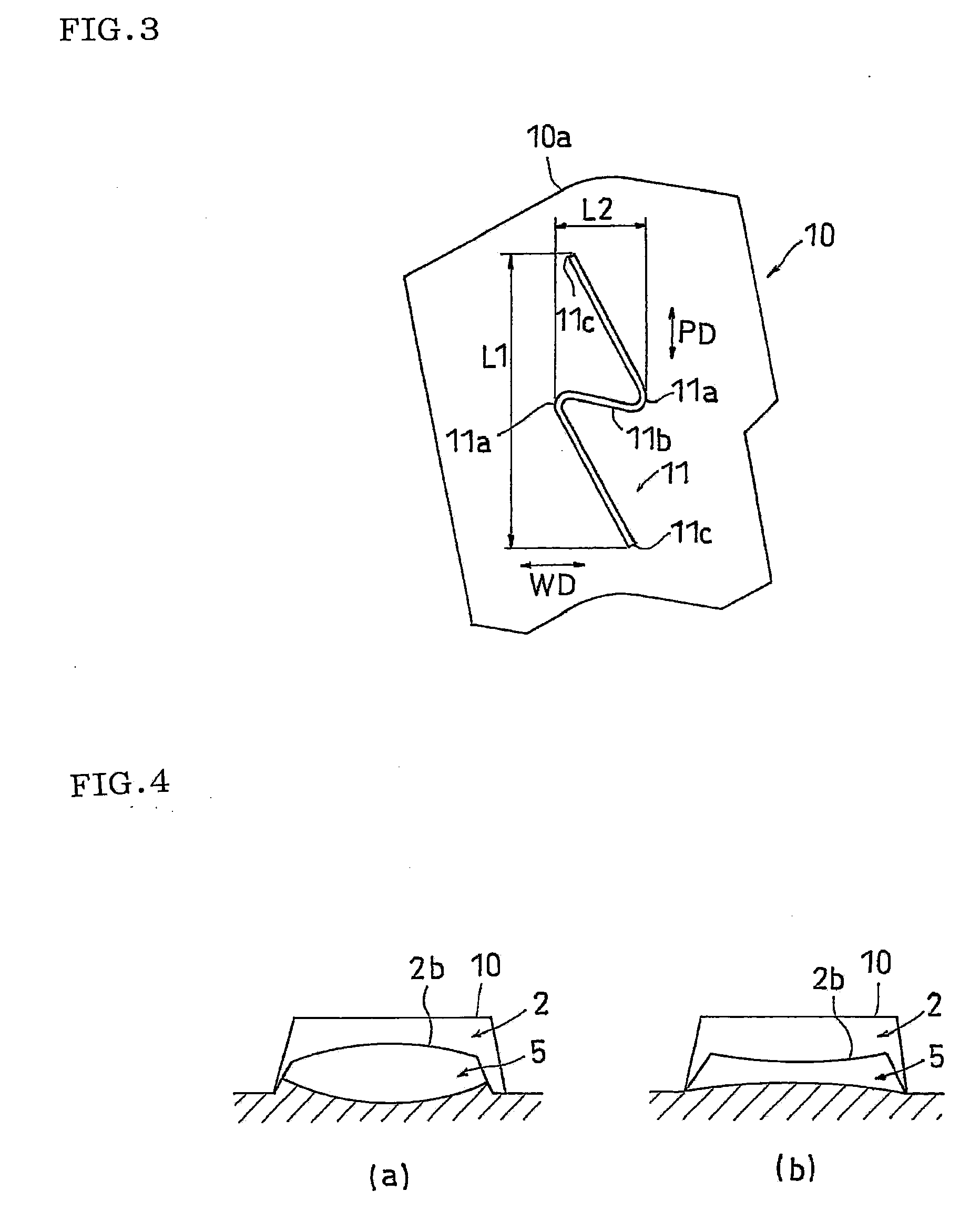
[0062]A radial tire having a size of 195/85R16 was produced by adjusting the depth of the circumferential groove to 12 mm, the groove width to 8.5 mm, the depth of the lateral groove to 6 mm, the groove width to 6 mm, the curvature radius of the bend section to 10 mm, the size of the block to approximately 34 mm×34 mm, the depth of the groove bottom sipe to 1.5 mm, the groove width to 0.6 mm, the depth of the land portion sipe to 6.5 mm, the groove width to 0.6 mm, L1=20 mm and L2=7.5 mm in the tread pattern shown in FIG. 1. The evaluation results on respective performance of the tire will be shown in Table 1.

PUM

no PUM

Description & Claims & Application Information

We can also present the details of the Description, Claims and Application information to help users get a comprehensive understanding of the technical details of the patent, such as background art, summary of invention, brief description of drawings, description of embodiments, and other original content. On the other hand, users can also determine the specific scope of protection of the technology through the list of claims; as well as understand the changes in the life cycle of the technology with the presentation of the patent timeline. Login to view more.

Similar technology patents

Rotating Swivel Assemblies for Outriggers

ActiveUS20170071178A1reduce wear
Owner:TACO METALS LLC

Low-dragging automotive disc floating brake and braking method thereof

InactiveCN106969067AReduce drag energy lossreduce wear
Owner:WUHAN UNIV OF TECH

Material scraping device

ActiveCN106881169AImprove the effective forcereduce wear
Owner:GUANGDONG SINID TECH

Classification and recommendation of technical efficacy words

  • easily move
  • reduce wear

Seed meter monitoring system

ActiveUS20070266917A1easily move
Owner:DEERE & CO

Canine Vest

InactiveUS20120024239A1quickly and easily placeeasily move
Owner:FORBES WILLIAM CHARLES

Movement assisting device and movement assisting method

InactiveUS20090276058A1easily moveeffective rehabilitation
Owner:PANASONIC CORP
Why Eureka
Try Eureka