Pre-wired power distribution system

a power distribution system and pre-wire technology, applied in the direction of electrical apparatus casings/cabinets/drawers, lighting conductor installation, coupling device connection, etc., can solve the problem of impracticality in testing each wired installation for conformance to construction standards

Inactive Publication Date: 2008-03-06
PROTECTCONNECT
View PDF99 Cites 36 Cited by
  • Summary
  • Abstract
  • Description
  • Claims
  • Application Information

AI Technical Summary

Benefits of technology

[0005] A pre-wired power distribution system, in contrast, advantageously combines installation flexibility, convenience and verifiability. A combination electrical box, plaster ring, one or more electrical devices installed in the plaster ring and one or more pre-wired grounds between the electrical box and the electrical device or devices provides for a pre-tested ground path. In an embodiment, the electrical device is a wiring module configured to accept any of various functional modules. The pre-wired ground also functions as a lanyard between the electrical device and the electrical box, allowing the plaster ring to be pivoted to, and s

Problems solved by technology

Further, it is impractical to test each wired inst

Method used


Image

  • Pre-wired power distribution system
  • Pre-wired power distribution system
  • Pre-wired power distribution system

Examples


embodiment 200

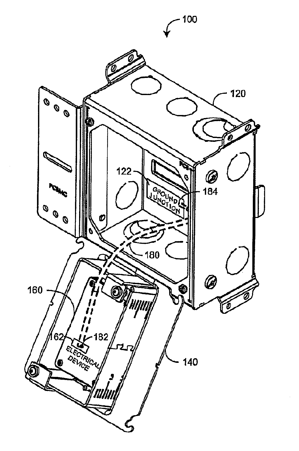
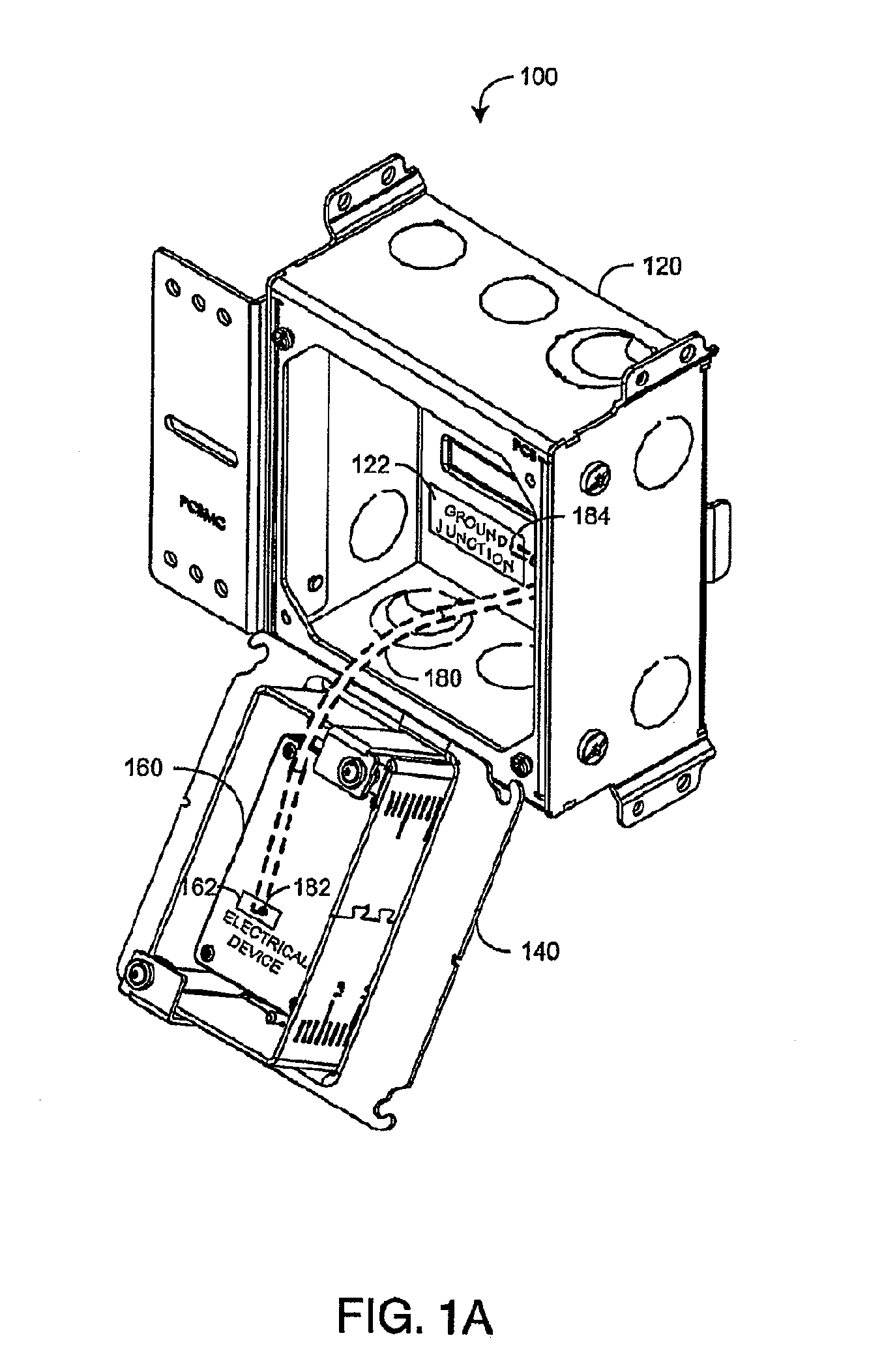
[0020]FIG. 2 illustrates a pre-wired power distribution system embodiment 200 having a wiring module 260 pre-wired with push-wire connectors 250. A ground wire 280 extends between the wiring module 260 and an electrical box 120. In some embodiments, the ground wire 280 includes a push-wire connector at some point along its length to be connected to a ground cable fed into the electrical box 120 along with other power distribution cables. The ground wire 280 has a first end 282 attached to a ground push-wire connector 252 and a second end 284 secured to a ground attachment point 222 in the interior of the electrical box 120. In some embodiments, the ground attachment point 222 is a screw terminal. The push-wire connectors 250 are connected to internal crimp wires of the wiring module 260 and adapted to accept power and ground wires from cables (not shown) routed to the electrical box 120. An electrician can easily and quickly attach the power wires to the appropriate push wire connec...

embodiment 300

[0021]FIG. 3 illustrates another pre-wired power distribution system embodiment 300 having a wiring module 360 with internal push-wire connectors 350. A ground wire 280 extends between the wiring module 360 and an electrical box 120. The ground wire 280 has a first end 282 attached to a ground push-wire connector 352 and a second end 284 secured to a ground attachment point 222 in the interior of the electrical box 120. The push-wire connectors 350 are adapted to accept power and ground wires from cables (not shown) routed to the electrical box 120.

[0022]FIG. 4A is a front perspective view of an embodiment of a wiring module 460 having internal push-wire connectors 407. The wiring module 460 has a mounting bracket 406 with an aperture 401 to mount the wiring module 460 to an adjustable plaster ring (e.g., 140) and an aperture 402 to attach a protective cover (e.g., 161) to the wiring module 460. The wiring module 460 also includes shielded connectors 403 for receiving a functional m...

embodiment 500

[0025]FIG. 5 illustrates a pre-wired power distribution system embodiment 500 having a 3-gang electrical box 520, a 3-gang adjustable plaster ring 540, a ground bus bar 550 mounted directly to the electrical box 520, three wiring modules 560 attached to the plaster ring 540 and a multiple wire ground lanyard 580. The ground lanyard 580 extends between the bus bar 550 and ground terminals 562 on each of the wiring modules 560. The bus bar 550 is configured to accept additional ground wires from power cables routed to and from the electrical box 520. As such, the ground lanyard 580 supports the plaster ring 540 in the open position shown, providing a wiring platform for the electrician to wire all three wiring modules 560 as a unit without having to handle and hold each of the wiring modules individually during the wiring process.

[0026] Advantageously, the bus bar 550 is configured to allow the attachment of multiple ground wires 580 so as to provide ground connections for not only wi...


PUM

PropertyMeasurementUnit
Massaaaaaaaaaa
Lengthaaaaaaaaaa
Forceaaaaaaaaaa

Abstract

A power distribution system has an electrical box configured to attach a power cable, a plaster ring releasably mounted to the box and one or more electrical devices installed into the ring. A pre-wired ground extends from a first end physically and electrically connected to a ground terminal on the electrical device. The plaster ring is movable between a closed position proximate the box and an open position distal the box. The pre-wired ground is configured as a lanyard so as to support the plaster ring as a wiring platform in the open position for connecting wires between the power cable and the electrical device or devices.

Description

CROSS-REFERENCE TO RELATED APPLICATIONS [0001] This application claims priority from U.S. Provisional Application No. 60 / 833,966 filed Jul. 29, 2006 and entitled “Pre-wired Power Distribution System,” which is incorporated by reference herein in its entirety. INCORPORATION BY REFERENCE [0002] Wiring modules and corresponding functional modules are described in U.S. Pat. No. 6,884,111 entitled Safety Module Electrical Distribution System, issued Apr. 26, 2005; U.S. Pat. No. 6,341,981 entitled Safety Electrical Outlet And Switch System, issued Jan. 29, 2002; and U.S. Pat. No. 6,894,221 entitled Safety Outlet Module, issued May 17, 2005. Modular electrical devices, electrical boxes and adjustable mounts are described in U.S. patent application Ser. No. 10 / 924,555 entitled Universal Electrical Wiring Component, filed Aug. 24, 2004. A wiring support platform is described in U.S. patent application Ser. No. 11 / 108,005 entitled Hinged Wiring Assembly, filed Apr. 16, 2005. All of the above-...

Claims


Application Information

Patent Timeline
IPC IPC(8): H01R13/502
CPCH01R9/24H01R13/502Y10T29/532H02G3/16Y10T29/49002H02G3/083Y10T29/49174H02G1/00H02G3/12H02G3/14H02G3/18H05K5/0008H05K5/0204
Inventor PURVES, STEVEGRUDT, DENNIS L.KARNS, JOHN
Owner PROTECTCONNECT
Why Eureka
Try Eureka