Muffler Device

a muffler and bracket technology, applied in the direction of machine/engine, machine supports, other domestic objects, etc., can solve the problems of limiting the space in a downward direction, the total space of the muffler and bracket cannot be effectively utilized, and the items attached to the muffler are stressed, etc., to achieve reliable fixing function, simple mounting, and cost-effective

Inactive Publication Date: 2008-03-06
VOLVO LASTVAGNAR AB
View PDF8 Cites 11 Cited by
  • Summary
  • Abstract
  • Description
  • Claims
  • Application Information

AI Technical Summary

Benefits of technology

[0004] The desire to fulfill legislation relating to emissions for environmental considerations, means that the introduction of catalytic exhaust filtration is increasing within the vehicle industry. This has the result that the components comprised in vehicles must be adapted to meet these new guidelines. In order to obtain exhaust gases with a relatively small amount of chemicals that are harmful to the environment, catalytic exhaust filtration is thus being introduced on increasing numbers of vehicle models. The muffler is therefore equipped with a catalyser and means for after-treatment of exhaust gases, which means that the container requires increased space for housing both muffling and catalytic exhaust filtration. In order to make room for a larger muffler, it is advantageous to utilize the available space more effectively. One way of doing this is to replace the known, bulky brackets with a space-saving bracket. Another way is to give the container a shape that utilizes the available space more effectively.
[0006] It is desirable to obtain a device that makes it possible to mount a container in a space-saving and simple way, so that the available mounting space is utilized in a maximal way and so that, at the same time, the container is held securely in a selected position. It is also desirable to obtain a method for mounting a container on a vehicle in a simple and ergonomic way, so that the available mounting space is utilized in a maximal way.
[0009] The bracket as a whole is thus intended to be positioned along one long side of an oval cylindrical container and the container is attached to the bracket at the places where the container is rounded. As the bracket essentially does not project beyond the extent of the container in a vertical direction, that is above or below the container, the container can be dimensioned so that it is a maximum size while retaining a reliable fixing function. As the container is only attached to the bracket at one long side, the container is simple to mount in the required position and, as a result of the bracket being single-sided, that is as a result of the bracket being positioned asymmetrically in relation to the container, the bracket is also cost-effective as only one bracket is required to support a container. An alternative is to arrange a bracket on both sides of the container for reasons associated with stresses, which would involve higher costs as more brackets would have to be produced and, in addition, more space would be taken up on the goods vehicle.

Problems solved by technology

With this type of bracket, the bracket requires a lot of space in a vertical direction, which means that the total space for the muffler and bracket can not be utilized effectively.
In addition, the requirement for ground clearance limits the space in a downward direction.
In addition, circular mufflers have the disadvantage that there is a danger that they will rotate in their fixing, which results in stresses on items attached to the mufflers, for example connecting cables.
In addition, from a purely technical point of view, obtaining sufficient space for mounting, during production, a muffler on a bracket that is to be placed above or below the muffler is complicated.
In addition, the actual bracket of the said type takes up a relatively large amount of space.
The muffler is therefore equipped with a catalyser and means for after-treatment of exhaust gases, which means that the container requires increased space for housing both muffling and catalytic exhaust filtration.
An alternative is to arrange a bracket on both sides of the container for reasons associated with stresses, which would involve higher costs as more brackets would have to be produced and, in addition, more space would be taken up on the goods vehicle.

Method used


Image

  • Muffler Device
  • Muffler Device
  • Muffler Device

Examples


Embodiment Construction

[0018] The embodiments of the invention with further developments described in the following are only to be regarded as examples and are in no way to limit the protection provided by the patent claims. In the embodiments described here, the same reference numerals in the different figures refer to the same type of component.

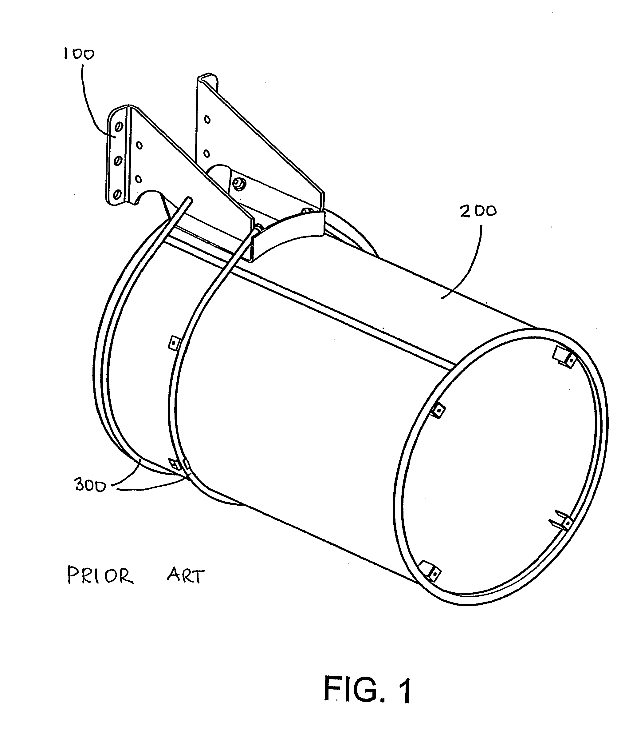
[0019]FIG. 1 shows a bracket 100 for attaching to a round muffler of the type that is currently in use. The muffler 200 is supported by a bracket 100 that projects above the muffler 200 and interacts with straps 300 that are attached to the outer ends of the bracket and, together with the bracket 100, surround the muffler 200 to attach this to the bracket 100.

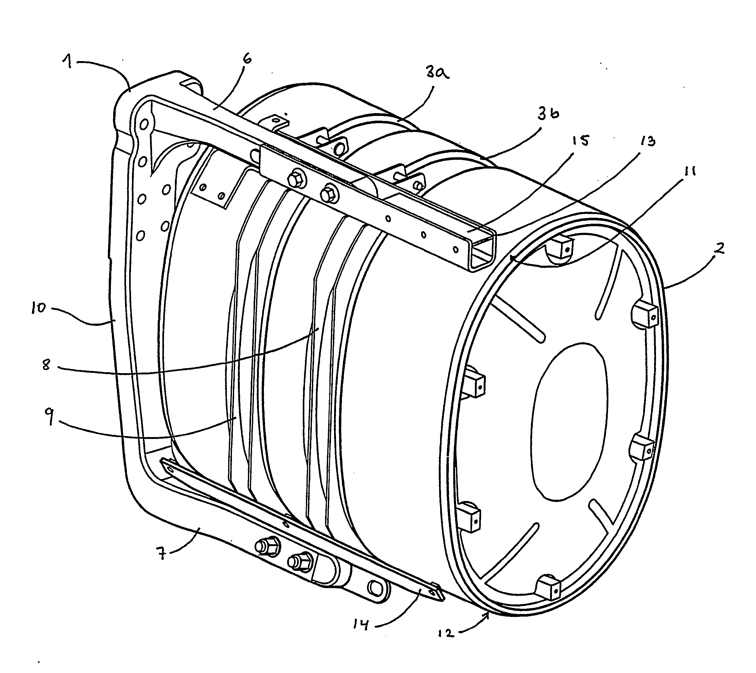
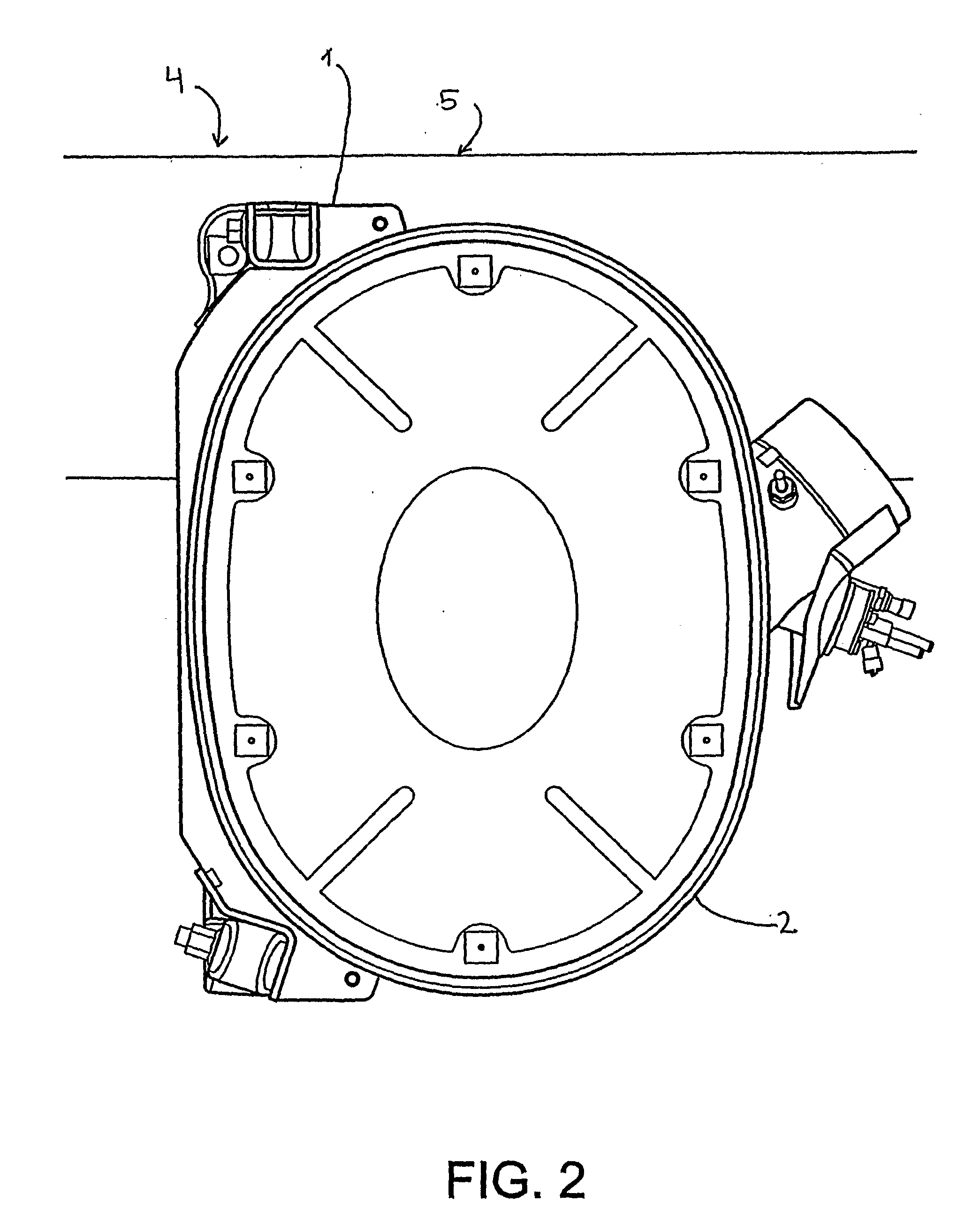
[0020]FIG. 2 shows a part of the side 4 of a heavy goods vehicle with a bracket 1 and an oval, cylindrical container 2 mounted in the bracket 1, which container contains muffler and catalyser and means for after-treatment (not shown). The bracket 1 is essentially mounted vertically with an upper arm and a ...


PUM


Abstract

A device for mounting an oval container on a motor vehicle includes a bracket designed to be mounted vertically on the frame of a vehicle, where the bracket includes an upper arm and a lower arm. The device also includes a mounting unit including a reinforcing beam designed to be mounted on the upper arm, a beam designed to be mounted on the lower arm and at least one strap holder designed to interact with a strap for attaching the said oval container. The reinforcing beam and the beam are permanently attached to the strap holder. A method for mounting an oval container on a vehicle is also disclosed. A simple and space-saving mounting of an oval container on a vehicle can be provided.

Description

BACKGROUND AND SUMMARY [0001] The present invention relates to a muffler device for a vehicle, in particular a device for supporting and attaching the muffler to the vehicle in the form of at least one bracket permanently attached to the vehicle, provided with means for attaching the muffler to the bracket. The invention also comprises a method for mounting the said muffler on a vehicle. [0002] The most common solution for mounting a muffler, in particular on heavy goods vehicles, is to use a bracket that projects over or under the muffler. The bracket interacts with straps that are attached to the outer ends of the bracket and that, together with the bracket, surround the muffler to attach it to the bracket. For this purpose, the muffler is usually round. With this type of bracket, the bracket requires a lot of space in a vertical direction, which means that the total space for the muffler and bracket can not be utilized effectively. In addition, the requirement for ground clearanc...

Claims


Application Information

Patent Timeline
Patent Type & Authority Applications(United States)
IPC IPC(8): B60K13/04F01N7/18B60K15/067F01N13/18
CPCB60K13/04B60Y2200/14B60K15/067
Inventor IVARSSON, ANDERSPUTTER, THOMAS
Owner VOLVO LASTVAGNAR AB
Why Eureka
Try Eureka