Integrated saw device heater

a saw device and heater technology, applied in the direction of impedence networks, electrical devices, etc., can solve the problems of excessive loss of heater power, unnecessary reliability degradation, and increase in the cost of the final product in the prior art, so as to achieve thermal stability faster, less costly, and reliable

Active Publication Date: 2008-03-06
RAYTHEON CO
View PDF11 Cites 4 Cited by
  • Summary
  • Abstract
  • Description
  • Claims
  • Application Information

AI Technical Summary

Benefits of technology

[0006]It is a further object of this invention to provide such a device in which the thermal resistance between the heat source and the SAW device is minimized.
[0013]The subject invention results from the realization that lower thermal resistance between the SAW device and its heater or heaters can be minimized resulting in lower heat losses, lower power requirements, faster thermal stability, increased reliability, lower costs, and increased ease of assembly by deposition of a heater element directly on the SAW device instead of mounting a heater on the electronic package housing the SAW device.

Problems solved by technology

The result in the prior art is a large thermal resistance between the SAW device and the heater resulting in excessive losses with commensurate increased time and / or heater power necessary to achieve required thermal stability.
Moreover, it may, in some instances, be undesirable to unnecessarily heat secondary electronic components associated with the SAW device as this incurs unnecessary reliability degradation.
Also, due to the additional components associated with the heater and the cost of hybrid heater devices themselves, the cost of the final product in the prior art increases as does the difficulty of assembly.

Method used


Image

  • Integrated saw device heater
  • Integrated saw device heater
  • Integrated saw device heater

Examples


Embodiment Construction

[0032]Aside from the preferred embodiment or embodiments disclosed below, this invention is capable of other embodiments and of being practiced or being carried out in various ways. Thus, it is to be understood that the invention is not limited in its application to the details of construction and the arrangements of components set forth in the following description or illustrated in the drawings. If only one embodiment is described herein, the claims hereof are not to be limited to that embodiment. Moreover, the claims hereof are not to be read restrictively unless there is clear and convincing evidence manifesting a certain exclusion, restriction, or disclaimer.

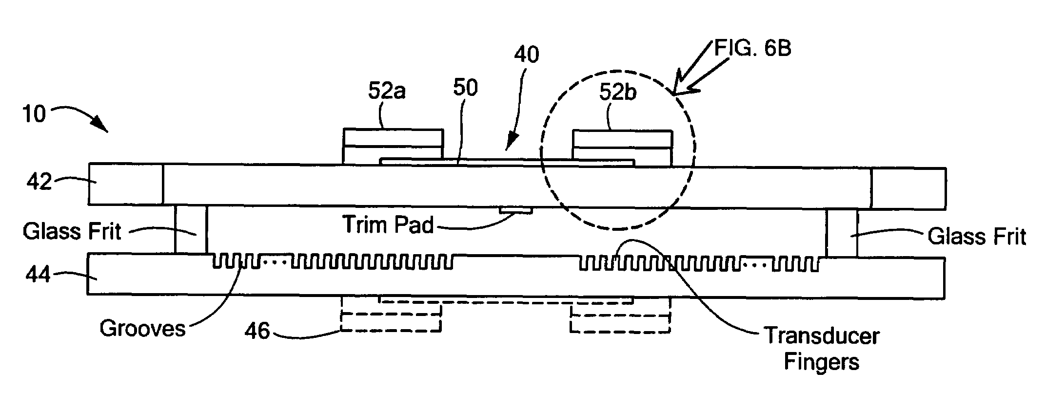
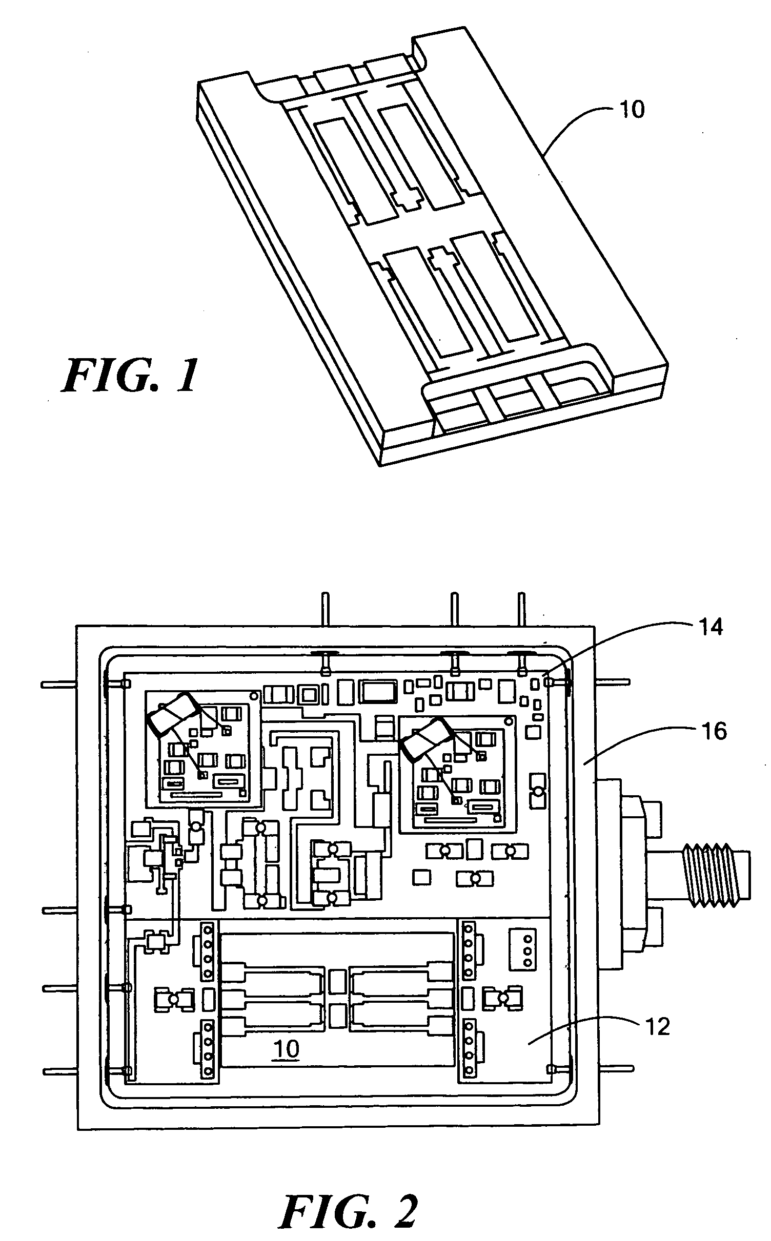
[0033]FIG. 1 shows one version of a SAW device 10 in accordance with U.S. Pat. No. 4,270,105 incorporated herein by this reference. FIG. 2 shows SAW device 10 mounted on circuit board 12 of electronic assembly 14 itself housed in oscillator package 16.

[0034]As described in the Background section above, SAW device 10 must be...


PUM


Abstract

An integrated SAW device features an electronic assembly, a SAW device mounted to the electronic assembly, and a heater element on the SAW device to minimize thermal resistance between the SAW device and the heater element.

Description

FIELD OF THE INVENTION[0001]The subject invention relates to surface acoustic wave (SAW) devices.BACKGROUND OF THE INVENTION[0002]A typical surface acoustic wave (SAW) device functions as a filter or a resonator for a specific range of radio frequency (RF) inputs. When implemented in the appropriate feedback circuit configuration, the SAW resonator along with associated electronic circuitry functions as an oscillator. When used as a serial component, the SAW resonator functions as a simple filter. Such electronic circuitry is usually embodied on a circuit board and housed within an enclosure.[0003]For high performance applications, the SAW device must be thermally stable to ensure stable RF performance. Typically, a heater element is physically coupled externally to the enclosure containing the SAW circuitry. In this way, the whole device package, supporting electronics and the SAW device within the package is heated and hence thermally stabilized. Alternatively, in some designs, on...

Claims


Application Information

Patent Timeline
Patent Type & Authority Applications(United States)
IPC IPC(8): H03H9/64
CPCH03H9/02834
Inventor KOEHNKE, MARK A.PEREIRA, STEPHEN J.
Owner RAYTHEON CO
Why Eureka
Try Eureka