System for clamping heat sink

a heat sink and heat sink technology, applied in semiconductor devices, electrical equipment, semiconductor/solid-state device details, etc., can solve the problems of heat generation in integrated circuits, damage to semiconductor devices, and harsh shock and vibration in automotive audio environments, so as to prevent excessive clamping force, minimize thermal resistance, and dissipate heat into the environment

Active Publication Date: 2011-11-08
HARMAN INT IND INC
View PDF1 Cites 2 Cited by
  • Summary
  • Abstract
  • Description
  • Claims
  • Application Information

AI Technical Summary

Benefits of technology

[0006]This invention provides a system for clamping a heat sink that prevents excessive clamping force. The system may include a heat sink, a semiconductor device, a printed circuit board, and a cover. The semiconductor device may be mounted onto the circuit board and attached to the cover. The heat sink may be designed to interface with the semiconductor device to transfer heat away from the semiconductor device and dissipate the heat into the environment. Accordingly, the heat sink may be clamped into a tight mechanical connection to minimize thermal resistance between the semiconductor device and the heat sink.
[0007]The clamping may be accomplished using bolts that are inserted through openings in the cover and threaded into the heat sink. Tightening the bolts may apply a clamping force that presses the heat sink against the semiconductor device. To prevent excessive clamping force from damaging the semiconductor device, loading columns may extend between the cover and the heat sink. The loading columns serve as a stop or structural support that act against the clamping force when the bolts are torqued. In addition, a button may be formed in the cover beneath the semiconductor device to act as a support for the semiconductor device. Further, a teardrop shaped support may be formed in the cover to support the printed circuit board. The teardrop shaped support may include a head portion with bolt openings and a tail portion that extends toward the semiconductor device to support the printed circuit board.

Problems solved by technology

When performing various functions, integrated circuits tend to generate heat.
For example, harsh shock and vibration are often encountered in an automotive audio environment.
However, clamping the semiconductor device with excessive force can cause damage to the semiconductor device.

Method used


Image

  • System for clamping heat sink
  • System for clamping heat sink
  • System for clamping heat sink

Examples


Embodiment Construction

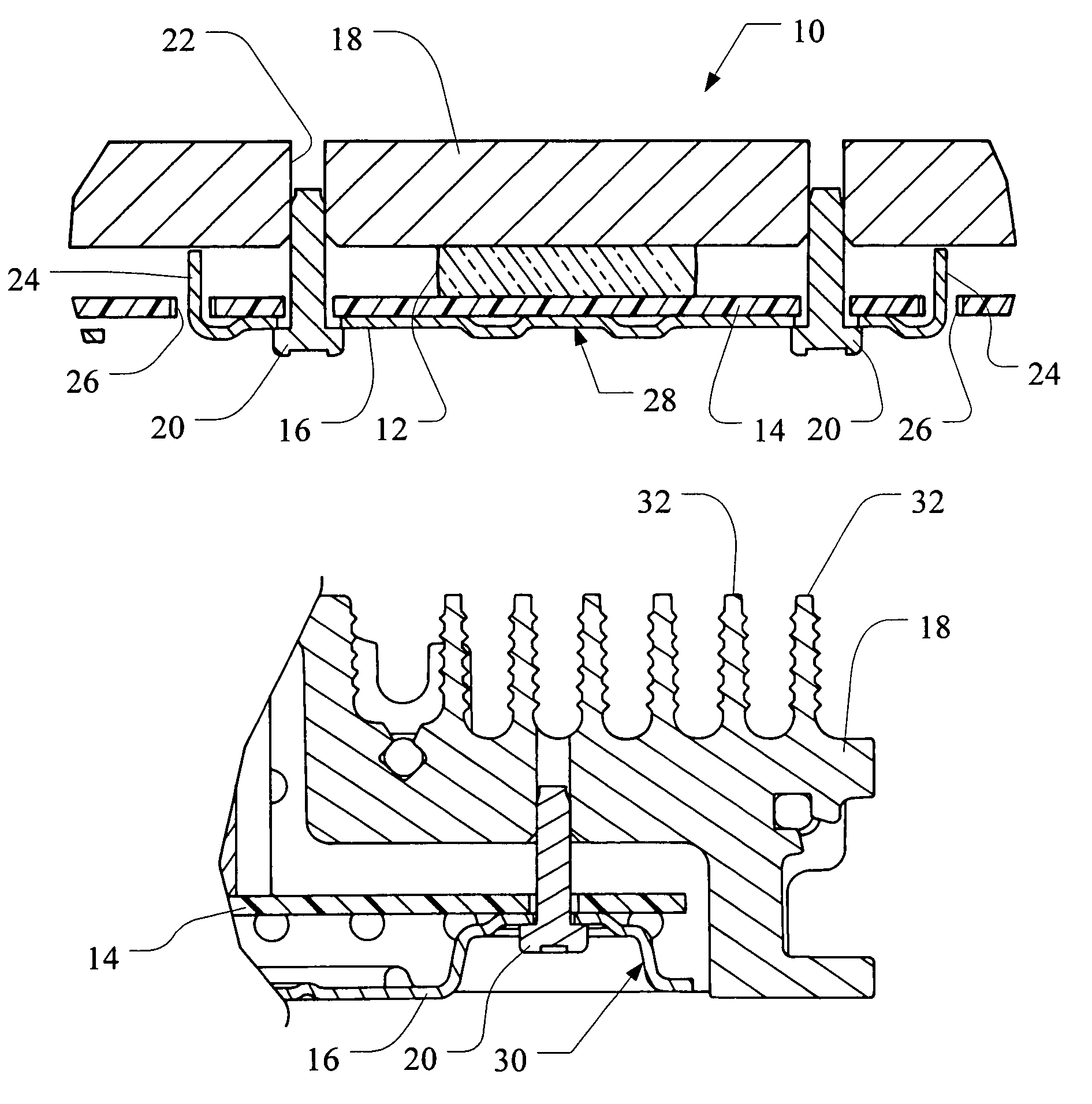
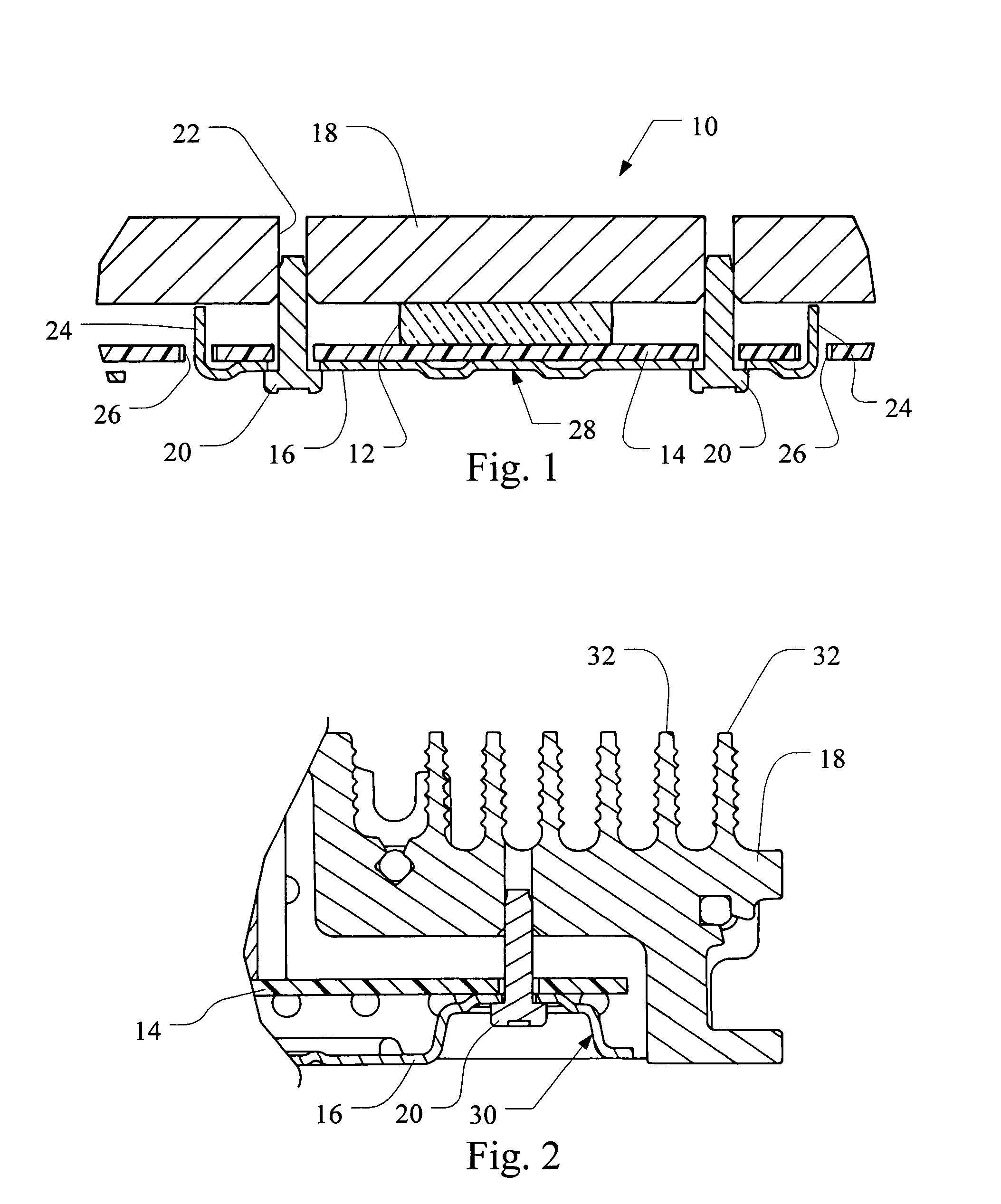
[0019]In FIG. 1, an example of an electronic assembly 10 is provided. The electronic assembly 10 may include a semiconductor device 12, a circuit board 14, a heat sink 18 and a cover 16. The semiconductor device 12 may be in the form of a power amplifier or other semiconductor device that generates heat during usage. These devices often include a ceramic casing and metal pins or pads for facilitating electrical connection. One such device may be the TDA8594J amplifier from PHILIPS electronics. Accordingly, the heat sink 18 may be provided to receive heat from the semiconductor device 12. The heat sink 18 transfers heat away from the semiconductor device 12 and provides an increased surface area allowing improved dissipation of the heat into the environment of the electronic assembly 10.

[0020]The electronic assembly 10 may also include a circuit board 14 such as a printed circuit board to which the semiconductor device 12 may be mounted. The circuit board 14 may be made of a plastic ...


PUM


Abstract

A system for clamping a heat sink that prevents excessive clamping force is provided. The system may include a heat sink, a semiconductor device, a printed circuit board, and a cover. The semiconductor device may be mounted onto the circuit board and attached to the cover. The heat sink may be designed to interface with the semiconductor device to transfer heat away from the semiconductor device and dissipate the heat into the environment. Accordingly, the heat sink may be clamped into a tight mechanical connection with the semiconductor device to minimize thermal resistance between the semiconductor device and the heat sink. To prevent excessive clamping force from damaging the semiconductor device, loading columns may extend between the cover and the heat sink.

Description

BACKGROUND OF THE INVENTION[0001]1. Technical Field[0002]The present invention is generally related to a system for clamping a heat sink. More specifically, the invention relates to a system for clamping a heat sink that prevents excessive clamping force.[0003]2. Related Art[0004]When performing various functions, integrated circuits tend to generate heat. The integrated circuit may be cooled by dissipating heat into the surrounding environment. Particularly in the audio electronics industry, the market has required manufacturers to provide smaller electronic packages along with improved audio performance and power. To improve heat dissipation, heat sinks or blocks of metal may be connected with semiconductor devices to conduct heat away from the semiconductor device and provide a larger surface area from which to dissipate the heat. The heat sink often include fins to increase the surface area for heat dissipation and may even include a channel that provides fluid cooling. This may...

Claims


Application Information

Patent Timeline
Patent Type & Authority Patents(United States)
IPC IPC(8): H01L23/34
CPCH01L23/4006H01L24/90H01L2924/01078H01L2224/73253H01L2224/90H01L2023/4056H01L2924/14H01L2924/00
Inventor MLOTKOWSKI, GREG
Owner HARMAN INT IND INC
Why Eureka
Try Eureka