
Lathe capable of automatically controlling workpiece clamping force and working method thereof

A technology of automatic clamping and clamping force, which is applied in the field of lathes to avoid deformation, improve work efficiency, and have wide applicability.

Pending Publication Date: 2021-06-01
旭淄机械(上海)有限公司
View PDF0 Cites 0 Cited by
  • Summary
  • Abstract
  • Description
  • Claims
  • Application Information

AI Technical Summary

Problems solved by technology

[0004] Purpose of the invention: the purpose of the invention is to provide a lathe and its working method that can automatically control the clamping force of the workpiece, which solves the problems that exist when the lathe is turned.

Method used


Image

  • Lathe capable of automatically controlling workpiece clamping force and working method thereof
  • Lathe capable of automatically controlling workpiece clamping force and working method thereof
  • Lathe capable of automatically controlling workpiece clamping force and working method thereof

Examples


Embodiment 1

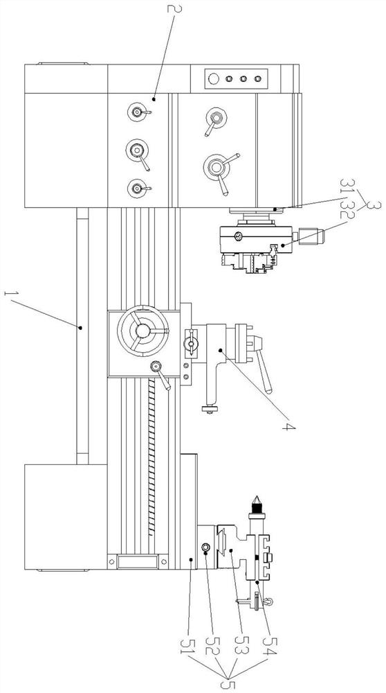
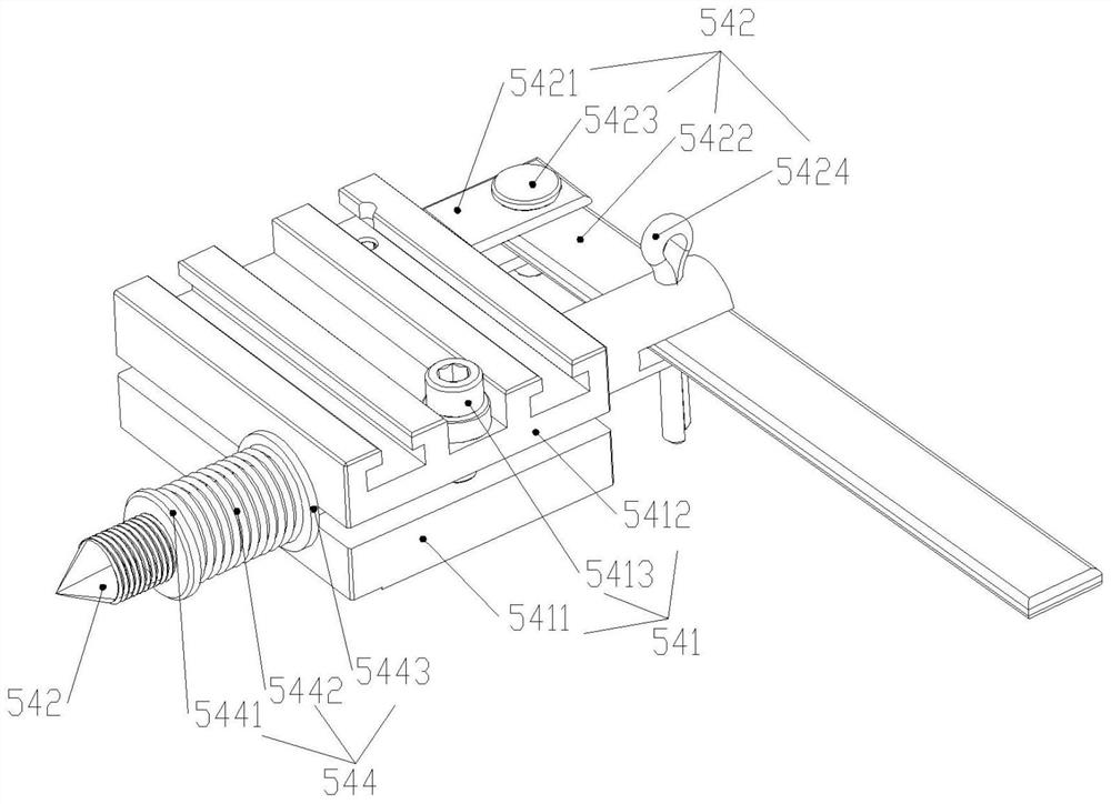
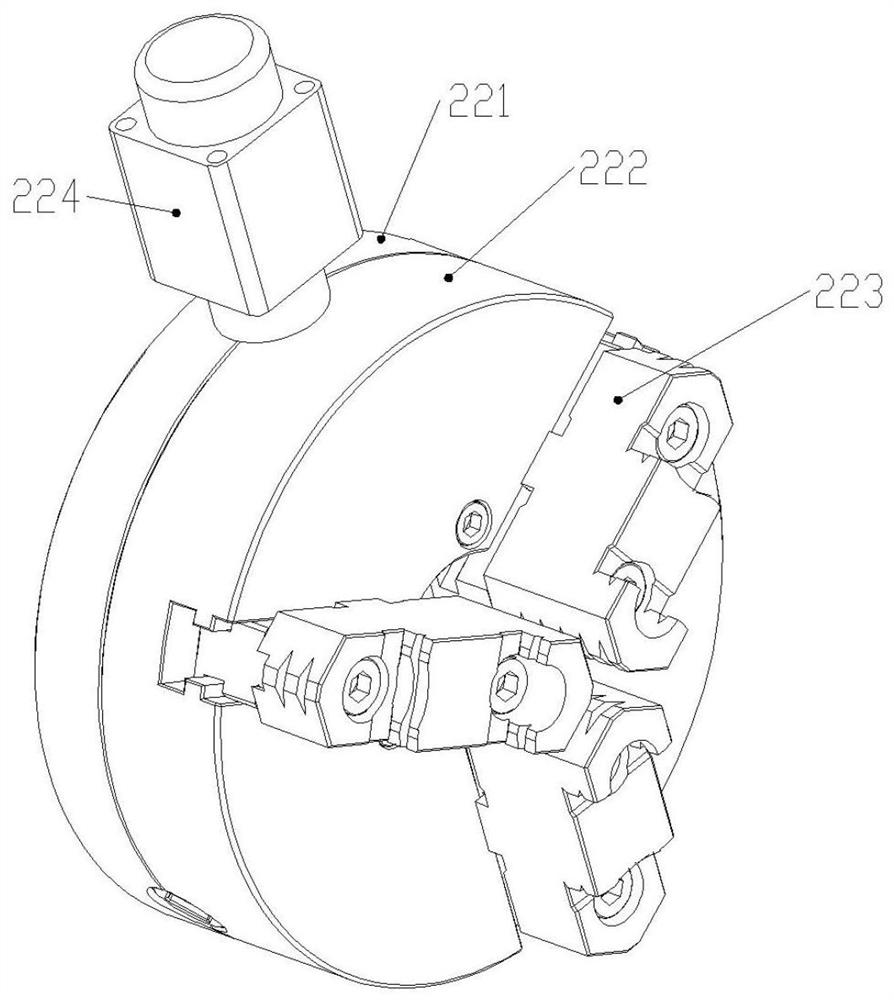
[0036] Such as figure 1 Shown is a front view of the present invention, including a lathe fixing seat 1, an end fixing structure 2, a feed structure 3, a tool rest structure 4, and a tailstock structure 5, and the end fixing structure 2 is arranged at the end of the lathe fixing seat 1 part, the feed structure 3 is arranged on the side of the lathe fixed seat 1, the tool rest structure 4 is arranged on the feed structure 3 above the lathe fixed seat 1, and the tailstock structure 5 is arranged on the lathe fixed seat 1 The other end away from the end fixing structure 2; the end fixing structure 2 includes a main shaft structure 21 and a chuck fixing structure 22, and the chuck fixing structure 22 is arranged at one end of the main shaft structure 21; the tailstock structure 5 includes a tail Seat guiding platform 51, first moving structure 52, second moving structure 53 and tail tightening structure 54, described first moving structure 52 is arranged on the tailstock guiding p...


PUM


Abstract

The invention discloses a lathe capable of automatically controlling workpiece clamping force and a working method thereof. The lathe capable of automatically controlling the workpiece clamping force comprises a lathe fixing base, an end fixing structure, a feeding structure, a tool rest structure and a tailstock structure; the end part fixing structure comprises a main shaft structure and a chuck fixing structure; and the tailstock structure comprises a tailstock guide table, a first moving structure, a second moving structure and a tail jacking structure. A workpiece needing to be machined is fixed through the end fixing structure and the tailstock structure, and the tool rest structure is driven by the feeding structure to move to a designated position according to the size needing to be machined, so as to perform turning work. Wherein one end of the workpiece is fixed through the chuck fixing structure in the end fixing structure, the tail jacking structure in the tailstock structure is driven by the first moving structure and the second moving structure to move to a designated position, so that the other end of the workpiece is pressed; and during turning, the workpiece is driven by the main shaft structure to rotate at a constant speed.

Description

technical field [0001] The invention relates to the field of lathes, in particular to a lathe capable of automatically controlling the clamping force of a workpiece and a working method thereof. Background technique [0002] With the rapid development of science and technology and social production, mechanical products are becoming more and more complex, and society has put forward higher and higher requirements for the quality and productivity of mechanical products. Especially in aerospace, shipbuilding, military and computer industries, the parts have high precision, complex shapes, small batches, many varieties, difficult processing, and high labor intensity. Traditional machining methods have been difficult to guarantee quality and the same parts. sex. [0003] The lathe is mainly used to rotate the workpiece with a turning tool, and it is one of the important equipment in the machining industry. The currently used lathes have the following deficiencies: 1) When turni...

Claims


Application Information

Patent Timeline
IPC IPC(8): B23B23/00B23B31/02B23B31/10B23B21/00
CPCB23B23/00B23B31/02B23B31/10B23Q1/00
Inventor 冯振复
Owner 旭淄机械(上海)有限公司
Learn More