Electric motor

a technology of electric motors and rotor cores, applied in the direction of magnetic circuit rotating parts, mechanical energy handling, shape/form/construction, etc., can solve the problems of damage, sealing problems, and the cooling fluid is not evenly distributed so as to reduce the pressure loss of the cooling passage provided in the rotor core, increase the cooling efficiency, and reduce the effect of heat generation

Inactive Publication Date: 2020-07-30
LG ELECTRONICS INC
View PDF0 Cites 5 Cited by
  • Summary
  • Abstract
  • Description
  • Claims
  • Application Information

AI Technical Summary

Benefits of technology

[0042]With this configuration, a flow of cooling fluid is branched in opposite directions at the central portion of the rotor core, thereby evenly distributing the flow of cooling fluid into the rotor core. In addition, problems such as vibration, noise, and, damage caused by an imbalance in flow rate may be solved. Further, a pressure loss of a cooling passage provided in the rotor core may be minimized.
[0043]Second, a cooling fluid supply pipe may be mounted inside a rotating shaft to be accommodated, and a plurality of cooling passages may be provided inside the rotor core to guide a cooling fluid into the rotating shaft and the rotor core. By doing so, the rotor, that causes high heat generation when an electric motor is driven at high speed, may be directly cooled down, thereby increasing cooling efficiency. As a result, driving stability and reliability of the electric motor may be enhanced, and driving efficiency of the electric motor itself may be increased.
[0044]Third, as a cooling fluid supply pipe in a rotating shaft and a cooling passage in the rotor core are located as close as possible to a cause of high heat generation (permanent magnet), thermal resistance between the cause of heat generation and a cooling fluid may be minimized, thereby increasing or maximizing rate (or speed) at which heat is removed.
[0045]Fourth, as the cooling fluid supply pipe having a small diameter is mounted in a hollow portion of the rotating shaft to be accommodated, and one end of the cooling fluid supply pipe is fixed to the housing, problems of friction and sealing between the cooling fluid supply pipe and the rotating shaft may be solved.
[0046]Fifth, a cooling fluid flowing along the hollow portion of the rotating shaft may evenly cool the entire rotating shaft. As an inner diameter of the hollow portion of the rotating shaft is larger (or greater) than the diameter of the cooling fluid supply pipe, an inner surface area of the rotating shaft that comes in contact with a cooling fluid may be increased, thereby enhancing a cooling effect.
[0047]Sixth, as a bearing cooling passage is provided inside a bearing accommodation portion to cool down a bearing, lifespan of the bearing may be extended, thereby increasing lifespan of the electric motor in overall.

Problems solved by technology

First, a cooling fluid is introduced into a rotating shaft through one end thereof, and is then distributed to a cooling passage in a rotor core from another end of the rotating shaft. However, the cooling fluid is not evenly distributed in the rotor core.
Accordingly, due to uneven flow distribution of cooling fluid, vibration and noise caused by mass imbalance of the cooling fluid during high-speed rotation may occur, thereby causing problems such as damage.
However, this may cause a sealing problem when the cooling fluid is introduced into the rotating shaft from a cooling fluid supply portion.
For example, since the rotating shaft rotates at a high speed and the cooling fluid supply portion is stationary, it is difficult to seal a cooling fluid supply pipe that connects between the rotating shaft and the cooling fluid supply portion.
In addition, friction may occur when the cooling fluid supply pipe is connected to the rotating shaft as it is rotatable.

Method used


Image

  • Electric motor
  • Electric motor
  • Electric motor

Examples


Embodiment Construction

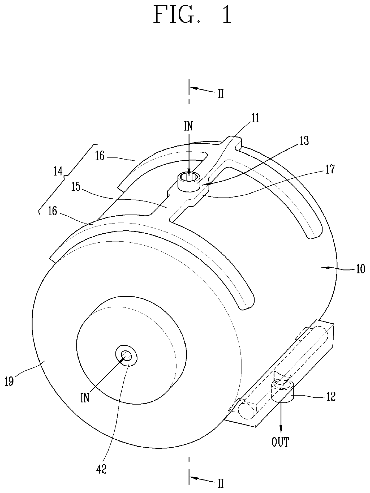
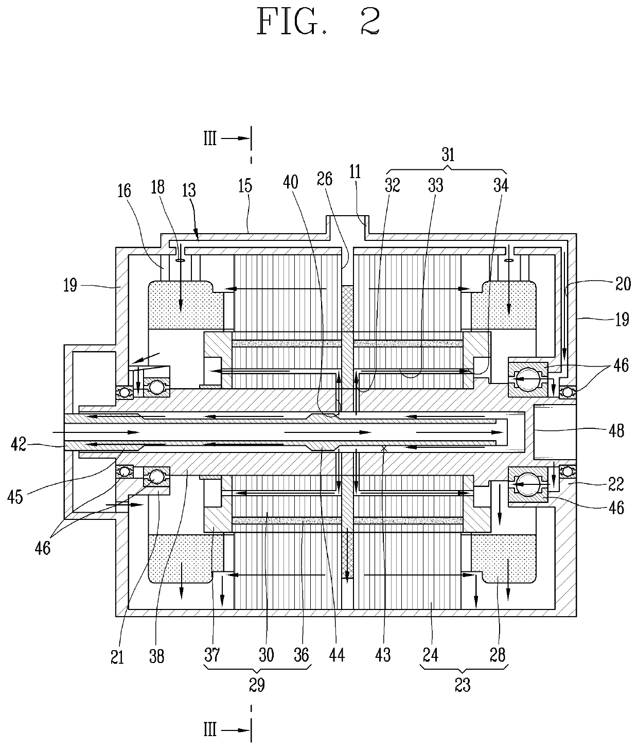
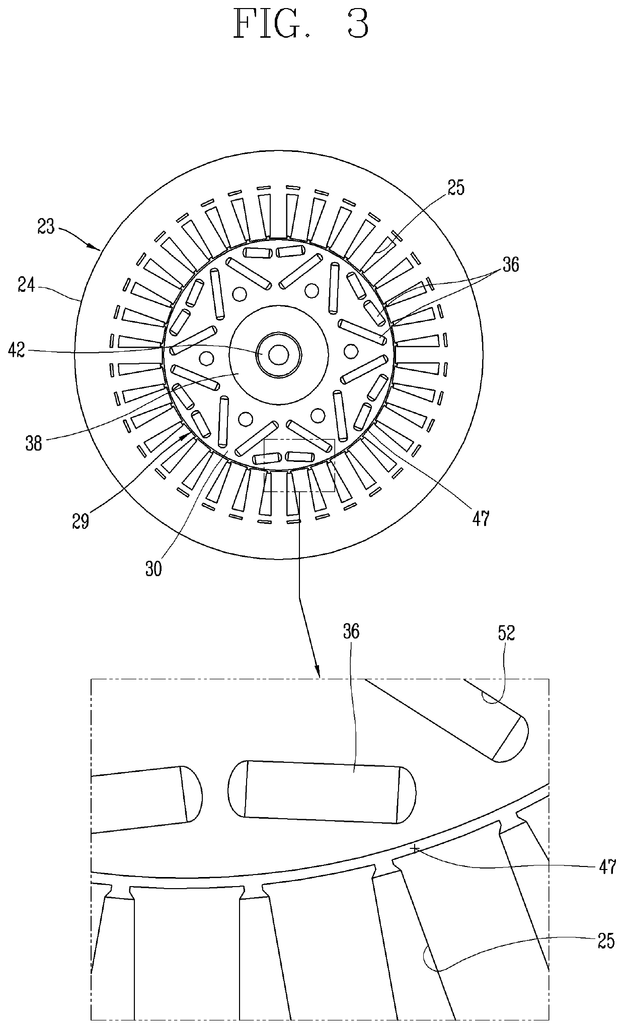
[0060]Hereinafter, embodiments will be described with reference to the accompanying drawings. In the drawings, the same or similar elements are designated with the same or similar reference numeral, and redundant description has been omitted. Suffixes, such as “module” and “unit”, may be used to refer to elements or components. Use of such a suffix herein is merely intended to facilitate description of the specification, and the suffix itself is not intended to give any special meaning or function. In describing embodiments, if a detailed explanation for a related known technology or construction is considered to unnecessarily divert the gist, such explanation has been omitted but would be understood by those skilled in the art. Also, it should be understood that the accompanying drawings are merely illustrated to easily explain the concept, and therefore, they should not be construed to limit the technological concept disclosed herein by the accompanying drawings, and the concept s...


PUM


Abstract

The present disclosure relates to an electric motor that may include a housing provided therein with an accommodating space; a stator having a stator core and provided in the accommodating space of the housing; a rotor having a rotor core and rotatably mounted inside the stator with an air gap therebetween; a rotating shaft provided therein with a hollow portion and having a plurality of rotating shaft injection holes formed at a central portion thereof, so that a cooling fluid introduced into the hollow portion is sprayed through the plurality of rotating shaft injection holes into the rotor core; and a plurality of cooling passages provided in the rotor core, and having one side thereof communicating with each of the plurality of rotating shaft injection holes and another side thereof communicating with the accommodating space, so that the cooling fluid is sprayed in different directions toward opposite ends to a central portion of the rotor core.

Description

CROSS-REFERENCE TO RELATED APPLICATION[0001]Pursuant to 35 U.S.C. § 119(a), this application claims the benefit of the earlier filing date and the right of priority to Korean Patent Application No. 10-2019-0009884, filed on Jan. 25, 2019, the contents of which is incorporated by reference herein in its entirety.BACKGROUND1. Technical Field[0002]The present disclosure relates to a motor for forming a flow path of the cooling fluid by forming a flow path inside the rotating shaft and the rotor core.2. Description of the Related Art[0003]An electric vehicle is an eco-friendly vehicle that uses only electricity as its source of energy and is driven by supplying an electrical energy to an electric motor from a high-voltage battery.[0004]In general, an electric motor includes a rotor and a stator. The rotor may be provided inside the stator in a rotatable manner.[0005]Technologies have been developed to cool down heat generated in the electric motor. Heat is generated in a stator coil, wo...

Claims


Application Information

Patent Timeline
Patent Type & Authority Applications(United States)
IPC IPC(8): H02K1/32
CPCH02K1/32H02K9/19H02K1/2766H02K9/12H02K1/20H02K7/003H02K5/203H02K1/28H02K2205/09
Inventor KANG, JOONYOON, JINHO
Owner LG ELECTRONICS INC
Why Eureka
Try Eureka