Electronic appliance

a technology of electronic appliances and slits, applied in the direction of insulated conductors, power cables, semiconductor/solid-state device details, etc., can solve the problems of ineffective transmission of heat of electronic components, insufficient heat dissipation effect, and inability to effectively dissipate heat, so as to reduce the increase of emi, increase an emi, and increase an emi due to the provision of slits

Inactive Publication Date: 2008-03-06
NINTENDO CO LTD
View PDF17 Cites 25 Cited by
  • Summary
  • Abstract
  • Description
  • Claims
  • Application Information

AI Technical Summary

Benefits of technology

[0023]By the way, as a result of forming a slit on the shield, an electromagnetic leakage might occur in the slit, and an EMI might be increased. In addition, the heat-dissipating member exposed from the slit functions as an antenna, which might further increase an EMI.
[0024]However, in the fifth invention, a ring-shaped ferrite is utilized as a magnetic member, so that the ground member becomes high loss at a high frequency band, and the electromagnetic waves at high frequency band are reduced. Thus, the increase in an EMI due to provision of the slit is reduced.
[0025]Such high-frequency noise absorption by ferrite extends to the electromagnetic waves generated when a high frequency current by the ESD flows through the shield, capable of enhancing an ESD resistance.
[0026]According to the present invention, effective heat dissipation can be performed, and a resistance to the electrostatic discharge is furthermore improved. In addition, electromagnetic interference is prevented.

Problems solved by technology

However, in a related art, if the heat-dissipating plate is provided on the underside, a substrate is inserted between the electronic component and the heat-dissipating plate, and therefore, heat of the electronic component is not necessarily effectively transmitted to the heat-dissipating plate, resulting in inadequate heat-dissipating effect.
On the other hand, in a case that the heat-dissipating plate is provided on the top surface, a heat-dissipating effect is high, but when an electrostatic discharge (Electro-Static Discharge: ESD) occurs, the electronic component is seriously damaged.

Method used


Image

  • Electronic appliance
  • Electronic appliance
  • Electronic appliance

Examples


Embodiment Construction

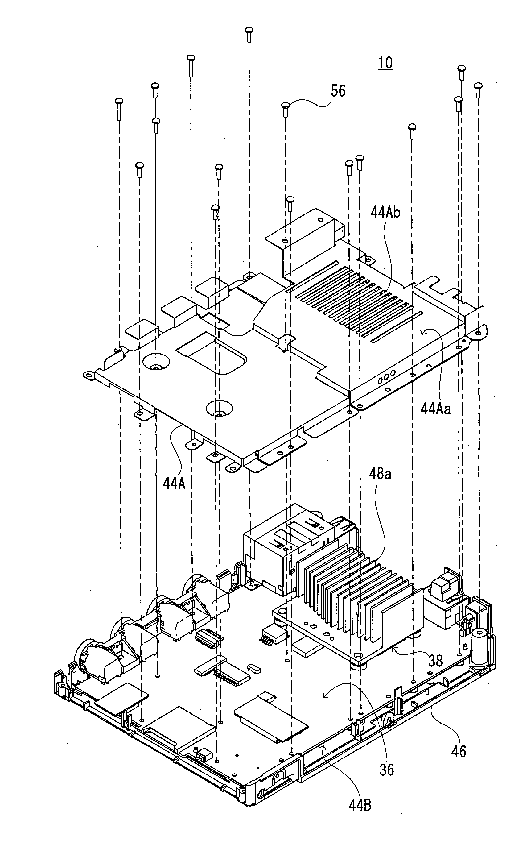
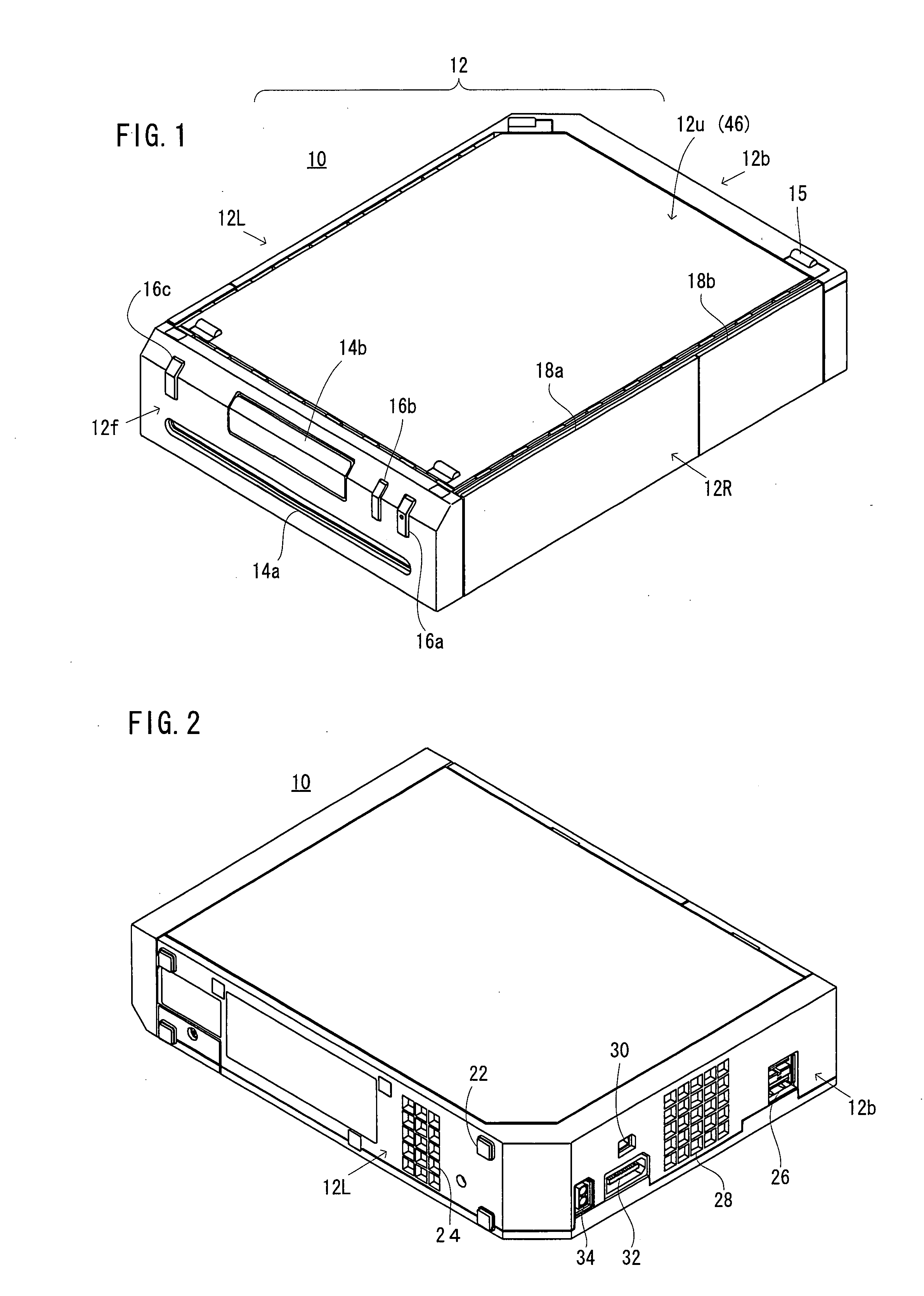
[0037]As shown in FIG. 1-FIG. 5, a game apparatus 10 of one embodiment of the invention includes a substantially rectangular housing 12. The housing 12 is formed by a plurality of metal plates and a plurality of metallic screws (not illustrated) for fixing them.

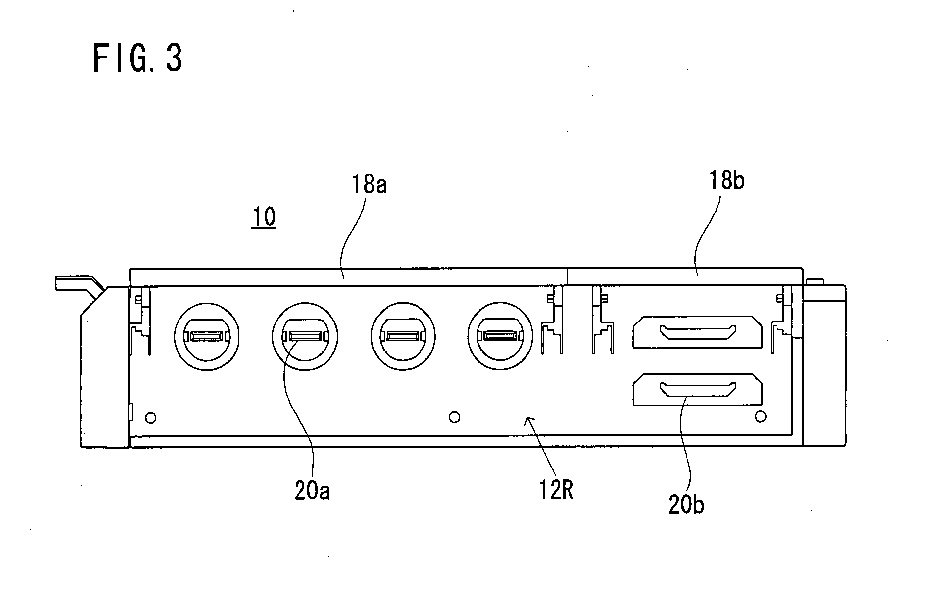
[0038]On a front surface 12f of the housing 12, disk slot 14a, an SD card slot cover 14b, a power button 16a, a reset button 16b, a disk eject button 16c, etc. are formed. On a right side surface 12R, openable closeable covers 18a and 18b, and a connector 20a for various controllers (not illustrated), a memory card slot 20b, etc. are provided. On the left side surface 12L, a rubber foot 22, an intake hole 24, etc. are provided. On a back surface 12b, a USB connector 26, an exhaust hole 28, a connector for peripheral equipment 30, an AV connector 32, a DC connector 34, etc. are provided. A bottom surface 12u is provided with a rubber foot 15, etc. The above-described metallic screws are hidden under the rubber foots 22 and 15....


PUM


Abstract

An electronic appliance includes a circuit board mounted with an electronic-circuit component. The circuit board is covered with a shield, and a metallic heat-dissipating member is arranged on the electronic-circuit component. The shield is grounded on the circuit board, and arranged such that at least one of the surfaces is in the vicinity of the heat-dissipating member. The heat-dissipating member is grounded on the circuit board by a ground member, and at the periphery of the ground member, magnetic members are arranged.

Description

CROSS REFERENCE OF RELATED APPLICATION[0001]The disclosure of Japanese Patent Application No. 2006-235940 is incorporated herein by reference.BACKGROUND OF THE INVENTION[0002]1. Field of the Invention[0003]The invention relates to electronic appliances. More specifically, the present invention relates to an electronic appliance having an electronic component and a heat-dissipating plate dissipating heat generated from the electronic component.[0004]2. Description of the Related Art[0005]As a conventional appliance of this kind, one disclosed in Japanese Patent Application Laid-Open No. 2004-303860 is widely known. In the related art, an electronic component is housed in a metallic electronic equipment housing so as to be mounted on a top surface of a two-layer substrate formed with a ground layer on the underside. A heat-dissipating plate is connected with each of the electronic equipment housing and the underside of the two-layer substrate (that is, ground layer). The heat generate...

Claims


Application Information

Patent Timeline
Patent Type & Authority Applications(United States)
IPC IPC(8): H05K7/20H05K9/00
CPCH01L23/467H01L2924/3011H05K1/0233H05K7/20409H05K9/0022H01L2924/0002H05K9/0067H01L2924/00
Inventor NAGAREDA, TAKESHIKITANO, YASUHISAHATTORI, SADAYOSHI
Owner NINTENDO CO LTD
Why Eureka
Try Eureka