Printer

a printing machine and printing plate technology, applied in the field of printing machines, can solve the problems of increasing the cost, and reducing the service life of the machine,

Active Publication Date: 2008-03-06
CASIO COMPUTER CO LTD
View PDF9 Cites 73 Cited by
  • Summary
  • Abstract
  • Description
  • Claims
  • Application Information

AI Technical Summary

Benefits of technology

[0012]It is therefore an object of the present invention to provide a size-reduced printer which sequentially prints different-color images in a supe

Problems solved by technology

Thus, it takes a relatively long time until a full color image has been printed.
In addition, the platen drum is required to be finished with high dimension accuracy, which increases the cost.
Further, clamps are

Method used


Image

  • Printer
  • Printer
  • Printer

Examples


first embodiment

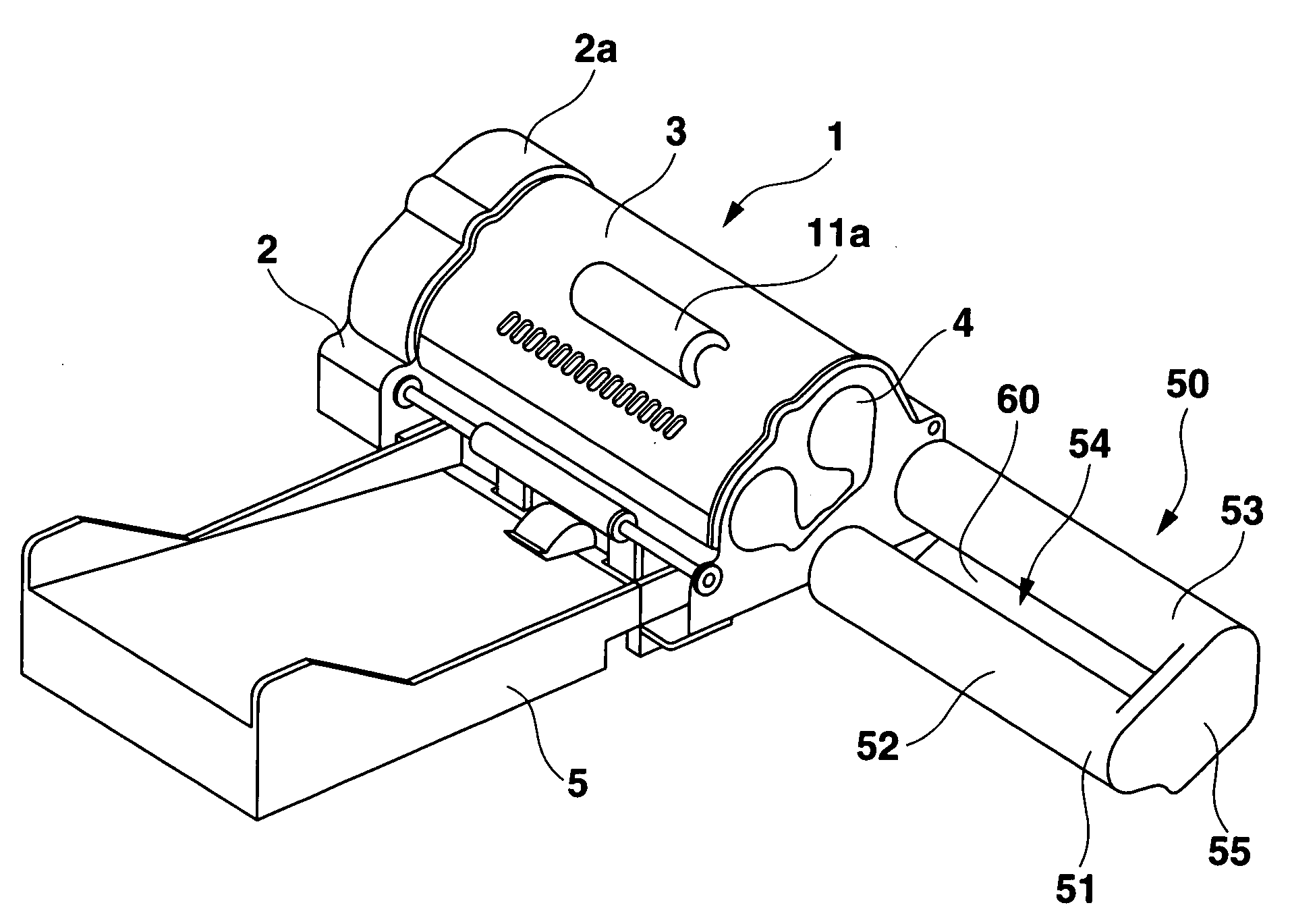
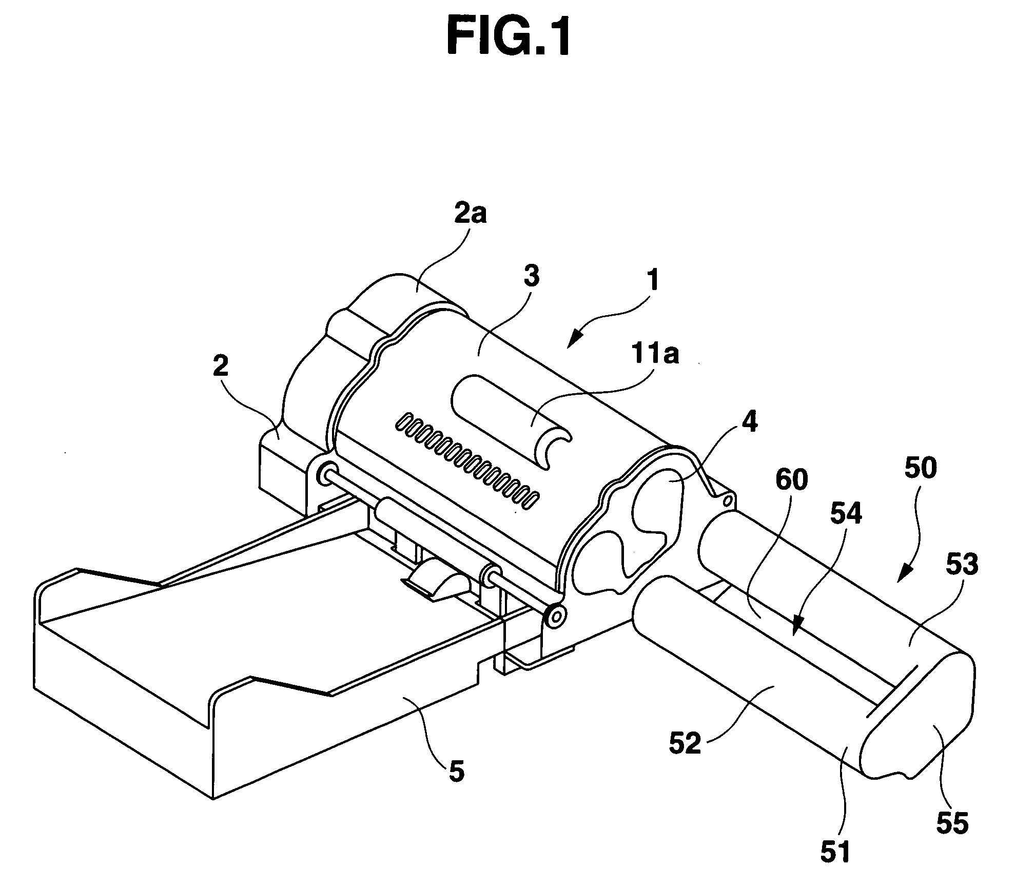
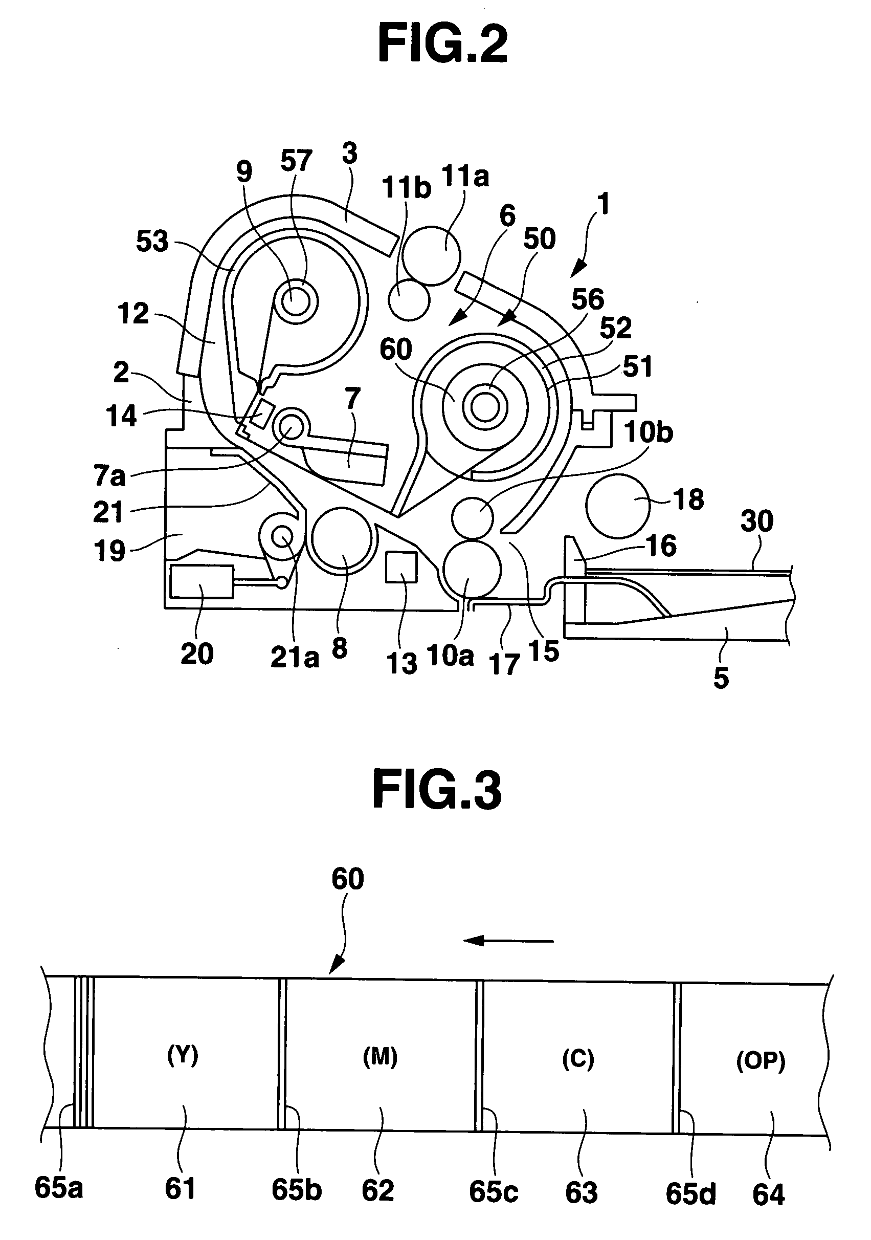
[0044]Referring to the drawings, the printers of the embodiments according to the present invention will be described. FIG. 1 is a perspective view of a printer of the present invention, and FIG. 2 is a schematic cross section view of the printer. This printer is a thermal transfer printer that causes a postal card- or L-sized photographic (or recording) sheet to be conveyed along a ring-like path a plurality of times such that a like number of different-colored images are sequentially printed in a superimposed manner on the sheet in a like number of different color inks contained in a multi-color ink ribbon. As shown in FIG. 1, the printer has a housing 1 which comprises a printer body 2 and a cover 3. The housing 1 has a cassette inlet 4 on one side thereof through which a ribbon cassette 50 that contains the multi-color ink ribbon 60 is insertable into the housing 1.

[0045]The ribbon cassette 50 inserted through the cassette inlet 4 into the housing 1 is loaded in a ribbon cassett...

second embodiment

[0071]FIG. 8 illustrates a flowchart of a printing process to be performed by the printer of the This printer has an electronic circuit similar to that shown in FIG. 4. The solenoid 69b is arranged to be controlled by the controller 80 so as to actuate the switching member 67. At the start of printing, the switching member 67 is switched so as to select the first conveyance path 12a, as shown in FIG. 7A. In FIG. 8, at the start of printing, one of recording sheets piled on the tray 5 is fed through the sheet inlet 15 into the printer housing 1 (step S21). At this time, the sheet sensor 13 senses the sheet type information printed on the sheet. Then, the controller 80 reads this information (step S22) and determines based on the information whether the recording sheet is the first recording sheet 30a (step S23). If so (YES in step S23), printing is performed on the first recording sheet 30a using the first conveyance path part 12a (step S24) in accordance with the processing steps s...

third embodiment

[0080]As shown in FIG. 12, the recording sheet 40 to be used in the printer of the third embodiment is disclosed, for example, in Unexamined Japanese Patent Application KOKAI Publication No.11-91170. A recording face 40a of the sheet has a heat-sensitive laminate of yellow, magenta and cyan layers 41, 42 and 43 of the same thickness provided on a sheet-like support 44 with the yellow layer 41 covered with a heat-resistant protective layer 45 where an upper surface of the protective layer 45 is the recording face 40a. Each of the yellow (Y), magenta (M) and cyan (C) heat-sensitive coloring layers 41-43 includes main coloring materials contained in respective small heat-sensitive capsules dispersed along with other components in a combining material. In order to control the coloring of the three Y, M and C layers with heat energy, their heat sensitivities are designed so as to decrease (or their coloring temperatures increase) in this order, as shown in FIG. 13. Thus, yellow, magenta ...


PUM


Abstract

A size-reduced printer that conveys a recording sheet in a circulating manner along a ring-like conveyance path while printing a plurality of images on the recording sheet in different colors sequentially in a superimposed manner, thereby forming a full color image. When a ribbon cassette that contains a multi-color ink ribbon is loaded at a predetermined position within a printer housing, a ring-like conveyance path is formed between the ribbon cassette and the printer housing. While the thermal head is driven and the recording sheet is conveyed once in a circulating manner along the conveyance path, a one-color image is printed on a previous printed one-color image in a superimposed manner in a corresponding one of the different color inks of the multi-color ink ribbon, thereby forming a full color image fully.

Description

BACKGROUND OF THE INVENTION[0001]1. Field of the Invention[0002]The present invention relates to printers that print a full color image in a plurality of colors and more particularly to such color printer having a reduced size.[0003]2. Background Art[0004]Generally, thermal printers comprise a thermal head that has a heating device and a conveyance device that conveys a recording sheet and a film-like ink ribbon coated with an ink. In the thermal printer, the ink ribbon is loaded between the recording sheet and the thermal head such that an ink of the ink ribbon is transferred to the recording sheet by the thermal head that is driven in accordance with print data, thereby forming an image. Especially, in a color thermal printer, a multi-color ink ribbon with yellow, magenta and cyan inks is used to print a image sequentially in yellow, magenta cyan inks in an superimposed manner, thereby printing a full color image.[0005]In the past, there are various thermal printers that print a c...

Claims


Application Information

Patent Timeline
IPC IPC(8): B41J2/325B41J31/00
CPCB41J2/325B41J2/36B41J13/009B41J13/0054B41J13/0045
Inventor YOKOYAMA, YOSHIMASA
Owner CASIO COMPUTER CO LTD
Why Eureka
Try Eureka