Centrifugal force-based microfluidic device for protein detection and microfluidic system including the same

a microfluidic device and centrifugal force technology, applied in the field of centrifugal force-based microfluidic devices for protein detection and microfluidic systems including the same, can solve the problems of difficult control of fluid flow and temperature of the functional units in the body of revolution

Active Publication Date: 2008-03-06
PRECISIONBIOSENSOR INC
View PDF6 Cites 105 Cited by
  • Summary
  • Abstract
  • Description
  • Claims
  • Application Information

AI Technical Summary

Benefits of technology

[0011]According to another aspect of the present invention, there is provided a microfluidic device including: a body of revolution having a rotation center and a circumference; a microfluidic structure disposed in the body of revolution comprising a plurality of chambers, channels connecting the chambers to each other and forming a path of fluid flow between the chambers, and valves disposed in the channels to control the fluid flow, the microfluidic structures transmitting fluid using centrifugal force due to rotation of the body of revolution, wherein one of the plurality of chambers receives a fluid biological sample; beads having a first probe to capture a target molecule from a fluid biological sample, the first probe selectively binds to the target molecule; and a second probe selectively binding to the target molecule and including a substance emitting an optical signal, wherein the microfluidic structure comprises: a sample chamber which receives a sample solution containing the fluid biological sample; a buffer chamber which receives a buffer solution; a bead chamber which receives a bead solution containing the beads; a mixing chamber which is fluid connected to the sample chamber, the buffer chamber, and the bead chamber through the channel; which receives a solution containing the second probe; which comprises an inlet to receive a fluid and an outlet to discharge the fluid, the outlet being disposed with a gre

Problems solved by technology

However, in this case, since a body of revolution is not fixed onto a frame and thus moves, it is

Method used


Image

  • Centrifugal force-based microfluidic device for protein detection and microfluidic system including the same
  • Centrifugal force-based microfluidic device for protein detection and microfluidic system including the same
  • Centrifugal force-based microfluidic device for protein detection and microfluidic system including the same

Examples


Embodiment Construction

[0046]Hereinafter, the present invention will be described more fully with reference to the accompanying drawings, in which exemplary embodiments of the invention are shown.

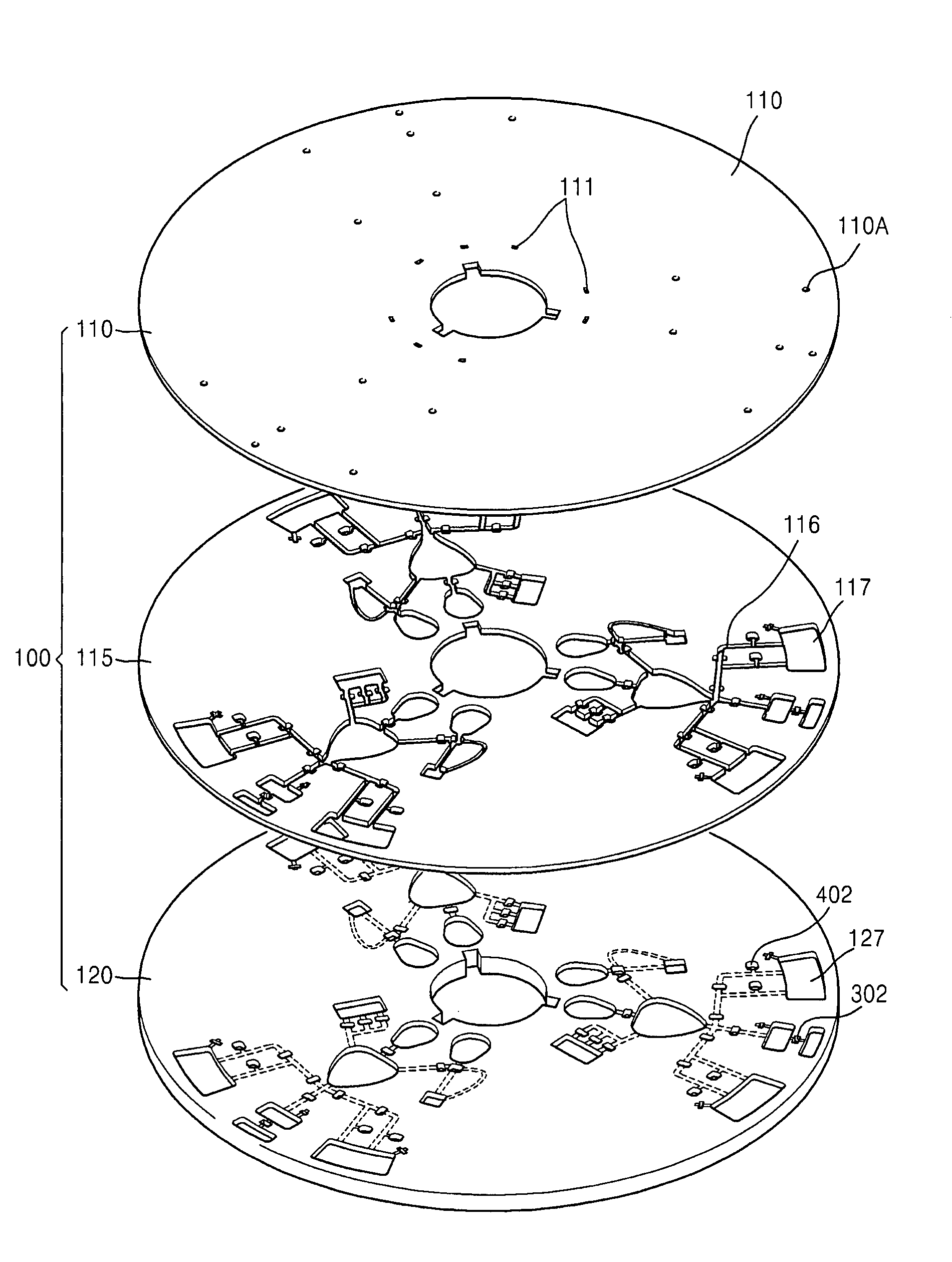
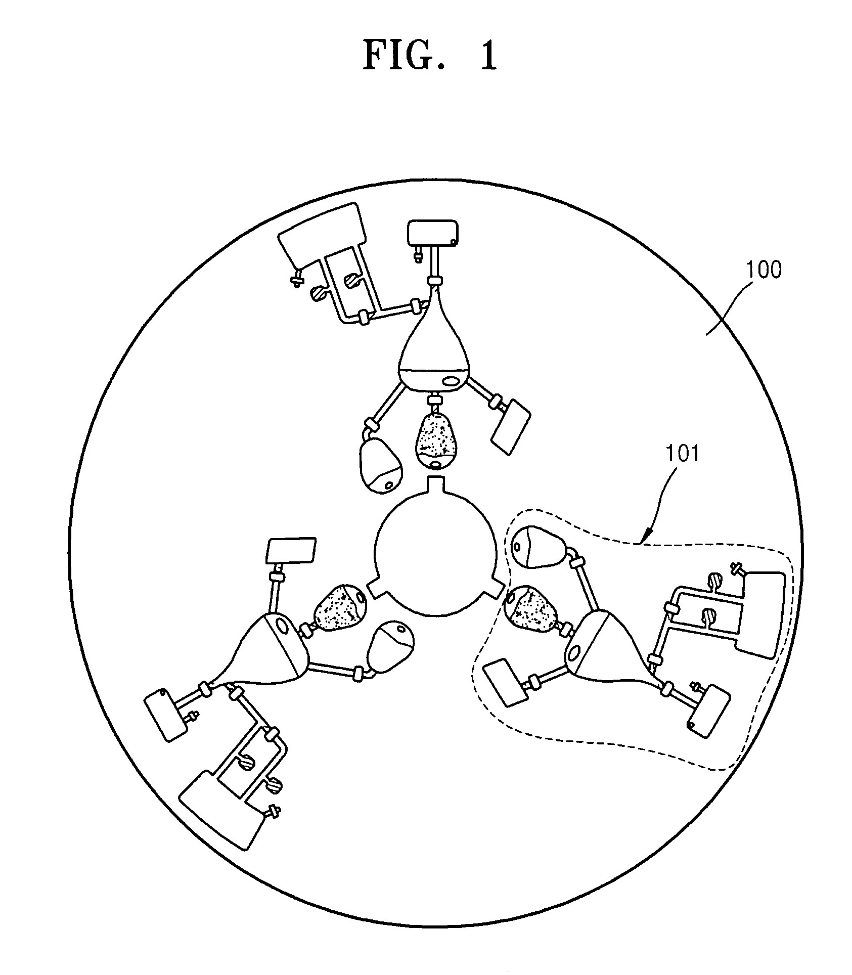
[0047]FIG. 1 is a plan view schematically illustrating a microfluidic device according to an embodiment of the present invention. Referring to FIG. 1, the microfluidic device includes a body of revolution 100 and one or more microfluidic structures 101 disposed on the body of revolution 100. According to the current embodiment of the present invention, the body of revolution 100 may be a disk-shaped platform. The platform can be easily manufactured and formed of plastic materials such as an acryl and PDMS and the surface of the platform is deactivated. However, the materials are not limited to the examples above and may be any materials having chemical and biological stability (i.e., inactivity), optical transparency, and mechanical processability. The body of revolution 100 may have a hole at the center thereof....


PUM


Abstract

A centrifugal force-based microfluidic device for the detection of a target biomolecule and a microfluidic system including the same are provided. The device includes a body of revolution; a microfluidic structure disposed in the body of revolution including chambers, channels connecting the chambers, and valves disposed in the channels to control fluid flow, the microfluidic structures transmitting fluid using centrifugal force due to rotation of the body of revolution; and beads disposed in the microfluidic structures, the beads having capture probes on the surfaces thereof which are selectively bonded with target protein; and a detection probe disposed in the microfluidic structures and selectively bonded to the target protein, and which includes a material required to express an optical signal, wherein the microfluidic structure mixes the beads, biological samples, and the detection probe to react and washes and separates the beads after the reaction.

Description

CROSS-REFERENCE TO RELATED PATENT APPLICATION[0001]This application claims the benefit of Korean Patent Application Nos. 10-2006-0085372, filed on Sep. 5, 2006 and 10-2007-0003401, filed Jan. 11, 2007, in the Korean Intellectual Property Office, the disclosures of which are incorporated herein in their entirety by reference.BACKGROUND OF THE INVENTION[0002]1. Field of the Invention[0003]The present invention relates to a centrifugal force-based microfluidic device which controls fluid flow by centrifugal force in a microfluidic structure prepared on a body of revolution. The present invention also relates to a centrifugal force-based microfluidic device for detecting target protein from a biological sample.[0004]2. Description of the Related Art[0005]In general, a microfluidic structure constituting a microfluidic device may include a chamber, a channel, a valve, and a plurality of functional units, wherein the chamber stores a small amount of fluid, the fluid flows through the chan...

Claims


Application Information

Patent Timeline
IPC IPC(8): B04B5/10
CPCB01L3/50273B01L3/502738B01L3/502761B01L2200/0647B01L2300/0806B01L2300/0867Y10T436/25375B01L2400/0409B01L2400/0633B01L2400/0677B01L2400/0688G01N33/54326G01N33/54366B01L2300/1861
Inventor LEE, BEOM-SEOKCHO, YOON-KYOUNGLEE, JEONG-GUNPARK, JONG-MYEON
Owner PRECISIONBIOSENSOR INC
Why Eureka
Try Eureka