
Liquid level measurement device and installation incorporating the same

a liquid level measurement and installation technology, applied in the direction of liquid/fluent solid measurement, water treatment parameter control, reradiation, etc., can solve the problems of cumbersome, time-consuming, and difficult liquid level check, and achieve the effect of quick and easy monitoring

Active Publication Date: 2008-03-13
ENG TECH CANADA
View PDF31 Cites 16 Cited by
  • Summary
  • Abstract
  • Description
  • Claims
  • Application Information

AI Technical Summary

Benefits of technology

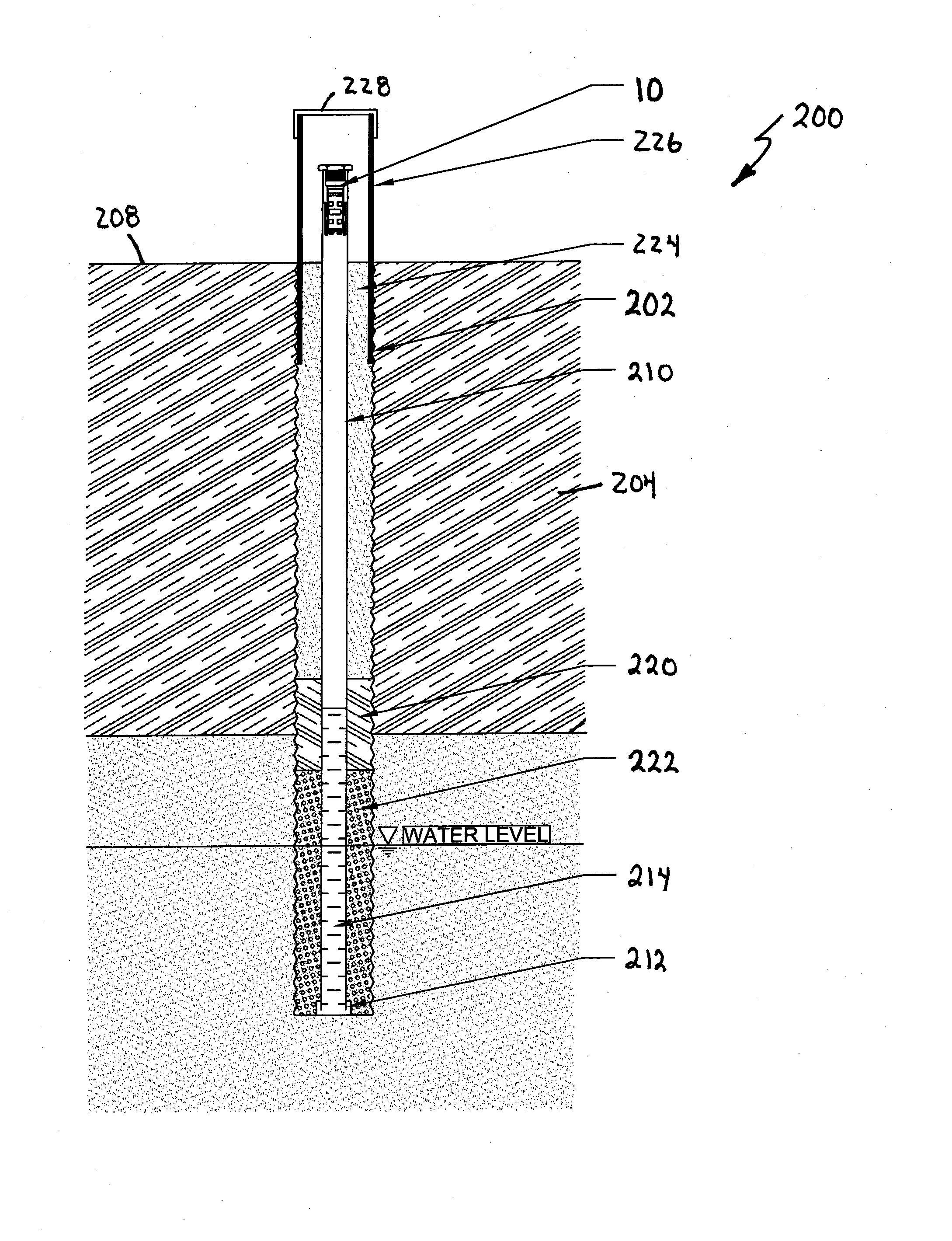
[0022] The liquid level measurement device is positioned within the pipe in a manner to inhibit interference. The liquid level measurement device is also positioned so that it typically remains spaced from liquid in the region.
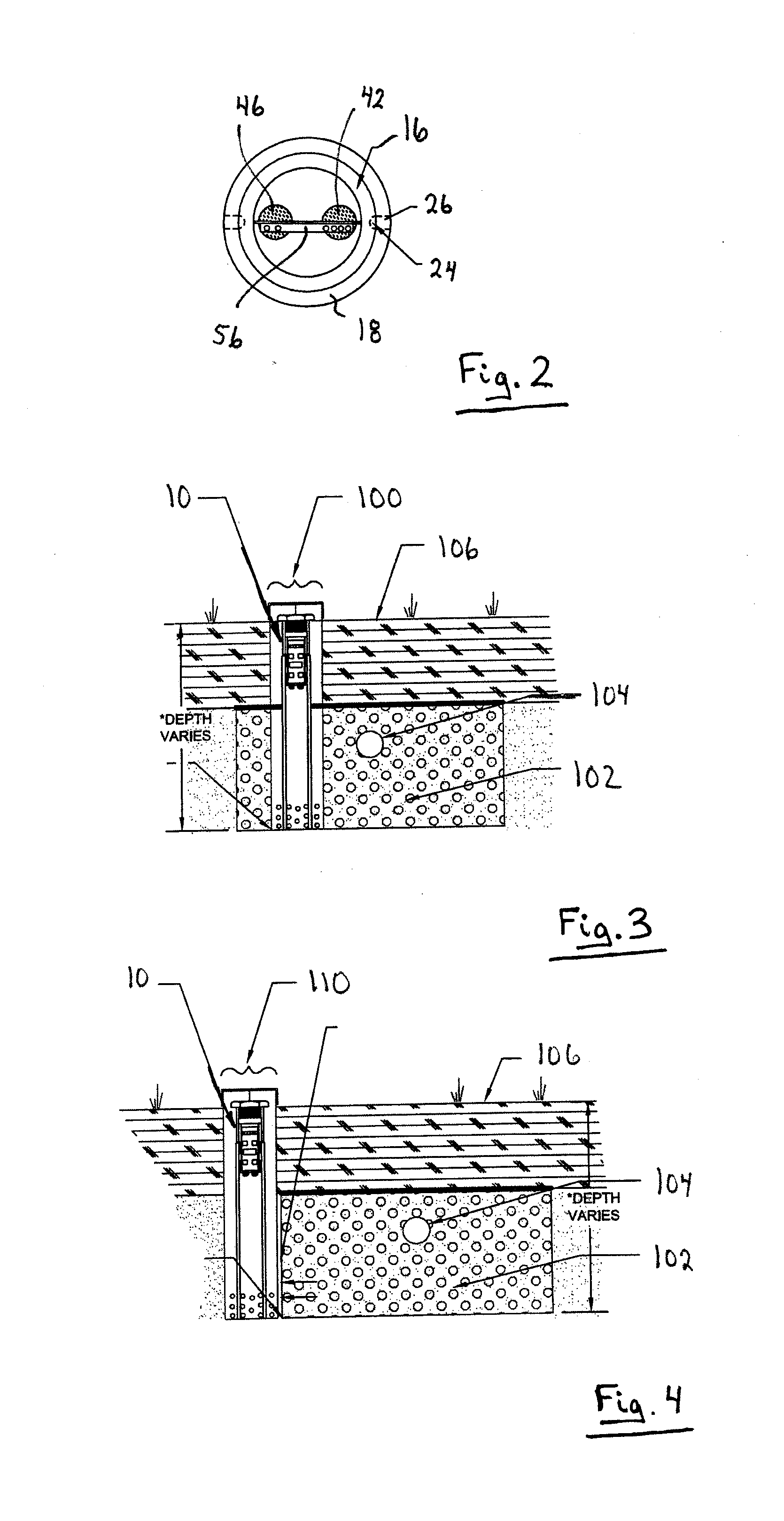
[0023] The liquid level measurement device allows the liquid level of an installation such as for example, an absorption field, groundwater well or the like, to be monitored quickly and easily on a regular basis allowing an alarm condition to be signaled should a high liquid level occur that exceeds a threshold level. In this manner, the owner / operator can be alerted to the high liquid level condition allowing the owner / operator to take remedial action if appropriate. The liquid level measurement device also allows historical liquid level data to be logged. In the case of absorption fields, the historical liquid level data can be used to plan the distribution of effluent to different trenches or beds and / or to determine if and when the absorption field needs to be expanded. In the case of groundwater level monitoring, historical data concerning groundwater levels can be maintained and provided to regulatory agencies if required. Also, as the liquid level measurement device employs a non-contact sensor, cross-contamination of groundwater from bacteria or viruses which may be present on the liquid level measurement device is avoided.

Problems solved by technology

In some instances however, owners of these installations bury the caps or plugs typically for aesthetic reasons.
This of course makes checking the liquid levels more difficult and time consuming.
Both of these conditions have serious negative public health and environmental impacts due to the possible presence of bacteria in the wastewater or effluent.
As will be appreciated, measuring liquid levels in this manner is time consuming, cumbersome and only provides liquid level measurements at snapshots in time.
Unfortunately, these float switches require large diameter tubes to provide for the minimum cord length required in order for the float to travel up and down.
Furthermore, as the float switches are in direct contact with the wastewater or effluent, the float switches are prone to fouling as a result of biological matter buildup on the float switches.
As with mechanical float switches, these pressure transducers are also prone to fouling as a result of biological matter buildup on the pressure transducers.
Unfortunately these pressure transducers tend to produce unreliable results once air pressures dissipate and equalize.

Method used


Image

  • Liquid level measurement device and installation incorporating the same
  • Liquid level measurement device and installation incorporating the same
  • Liquid level measurement device and installation incorporating the same

Examples


Embodiment Construction

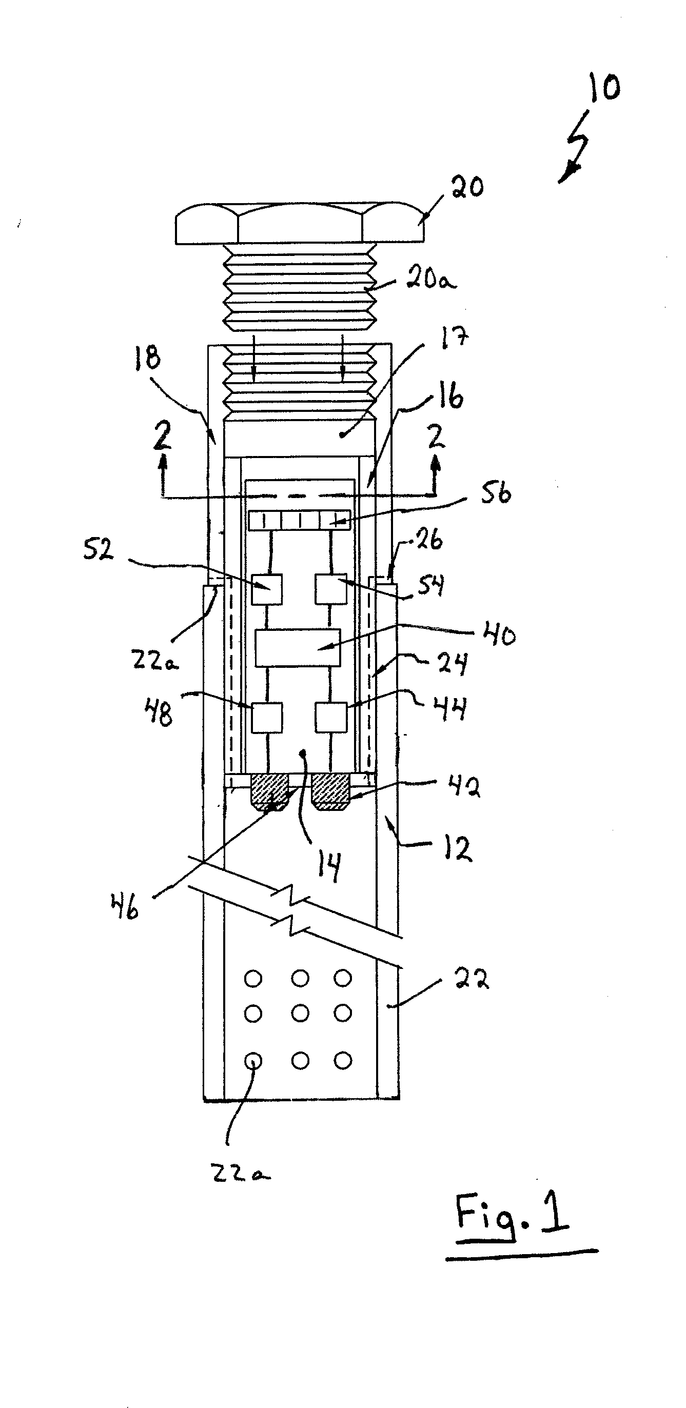
[0033] Turning now to FIGS. 1 and 2, a liquid level measurement (LLM) device designed to determine the distance to or height (some referred to as “ponding level”) of a liquid within an installation such as for example, an absorption field, groundwater well or other well, subsurface wastewater, septic or stormwater distribution trench or bed or the like, is shown and is generally identified by reference numeral 10. In this embodiment, the LLM 10 is to be inserted into an inspection port of an absorption field or the like and to sense the liquid level therein. As can be seen, LLM device 10 comprises a sensor assembly 12 mounted on a circuit board 14 disposed within an inner plastic sleeve 16. The circuit board 14 is suspended from a cap 17 at the top of the inner sleeve 16. An outer sleeve 18 is pressed onto and surrounds the upper portion of the inner sleeve 16. The interior wall of the outer sleeve 18 adjacent its upper end is threaded and receives a cap 20. Cap 20 comprises a threa...


PUM


Abstract

A liquid level measurement device comprises a generally seamless pipe for insertion into an installation in which liquid level is to be monitored and a non-contact sensor assembly disposed within the pipe at a location spaced above the liquid. The sensor assembly senses the level of the liquid and generates output representative of the liquid level.

Description

CROSS REFERENCE TO RELATED APPLICATIONS [0001] This application claims the benefit of U.S. Provisional Application Ser. No. 60 / 838,881 filed on Aug. 21, 2006 and U.S. Provisional Application Ser. No. 60 / 924,270 filed on May 7, 2007, the contents of which are incorporated herein by reference.FIELD OF THE INVENTION [0002] The present invention relates generally to measuring devices and in particular, to a liquid level measurement device and an installation incorporating the same. BACKGROUND OF THE INVENTION [0003] Systems to disperse or treat household wastewater, sewage, stormwater and the like (hereinafter referred to as “waste water”) are well known in the art. For example, one conventional system for disposing with or dispersing wastewater comprises a septic tank receiving wastewater from the structure serviced by the treatment system, a distribution box receiving effluent from the septic tank and a subsurface absorption field receiving the effluent distributed by the distribution...

Claims


Application Information

Patent Timeline
IPC IPC(8): G01F23/00G01F23/296
CPCC02F2209/42G01F23/2968G01F23/2962G01F23/0061
Inventor GALLOWAY, IAINGALLOWAY, KELLY
Owner ENG TECH CANADA
Learn More