
Portable metal compacting device

Inactive Publication Date: 2008-03-13
RAILSBACK DAN
View PDF7 Cites 7 Cited by
  • Summary
  • Abstract
  • Description
  • Claims
  • Application Information

AI Technical Summary

Benefits of technology

[0014]The present invention thus provides an improved metal crushing device which is superior in many respects to those devices currently found in the prior art. For example, the multiple hydraulic pistons connected to the movable inner top wall will drive the inner top wall downwards to evenly crush material regardless of the position of the material within the crush chamber prior to crushing. Furthermore, because the guide structure mounted atop the movable inner top wall prevents significant shifting of the movable top wall during the crushing process, the wear and tear on the hydraulic cylinders is greatly reduced, particularly as compared to the prior art. Also, because the present invention includes both an inlet door and an outlet door, it is very easy for a user of the device to quickly and easily load metal objects to be crushed into the device and, once the crushing process is completed, the user need not reposition himself or herself to unload the metal crushing device of the present invention, as the unloading takes place via the outlet door. Finally, because the present invention utilizes four upright hydraulic pistons which drive the inner top wall downwards to crush metal, the inner top wall does not have to be as heavy and large as those crush plates required by devices found in the prior art, which substantially decreases the overall weight of the improved metal crushing device of the present invention, thus making the device easier to transport and more efficient to operate. It is thus seen that the present invention provides a substantial improvement over those devices found in the prior art.

Problems solved by technology

When these are received at a landfill site, they are gathered together and moved into a transport truck for transport to a recycling center, but due to the large, bulky shape of most of the metal waste, it is somewhat difficult to transport the metal waste economically.
While these devices are usable for the purpose of compacting metal into more easily manipulated bundles and plates, they include specific design defects which render them operatively insufficient for their appointed task.
Specifically, the Lindemann patent utilizes a single hydraulic piston to drive the crushing ram and the Chazen patent discloses a ram having two cylinders for performing the crushing operation, which, in either situation, can result in an unbalanced load being crushed should the majority of the material to be crushed be pre-positioned above or below the point of connection of the hydraulic rams to the crush plate.
To compensate for this potential problem, the cited patents, in accordance with several other devices found in the prior art, suggests the use of a crush plate which is exceedingly large and heavy, with the end result being that the entire unit is thus quite large and difficult to move to various locations.
Another problem encountered in the prior art is that the vast majority of metal crushing devices are not designed to be portable for on-site use, as would be beneficial when the metal crushing device is to be used at a landfill site.
Such devices are not currently found in the prior art, with the main reason for this being that the need for such a device has heretofore been somewhat limited, in that the growth in the number and size of landfills is a relatively recent phenomenon.
However, this does not change the fact that there is a significant need for such a metal crushing device, a need which is not currently addressed and solved by the prior art.

Method used


Image

  • Portable metal compacting device
  • Portable metal compacting device
  • Portable metal compacting device

Examples


Embodiment Construction

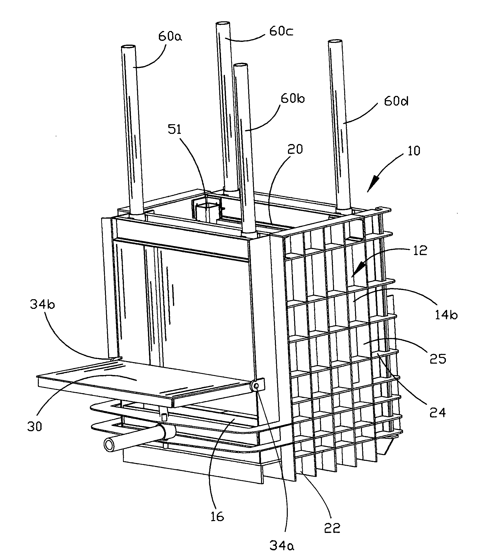
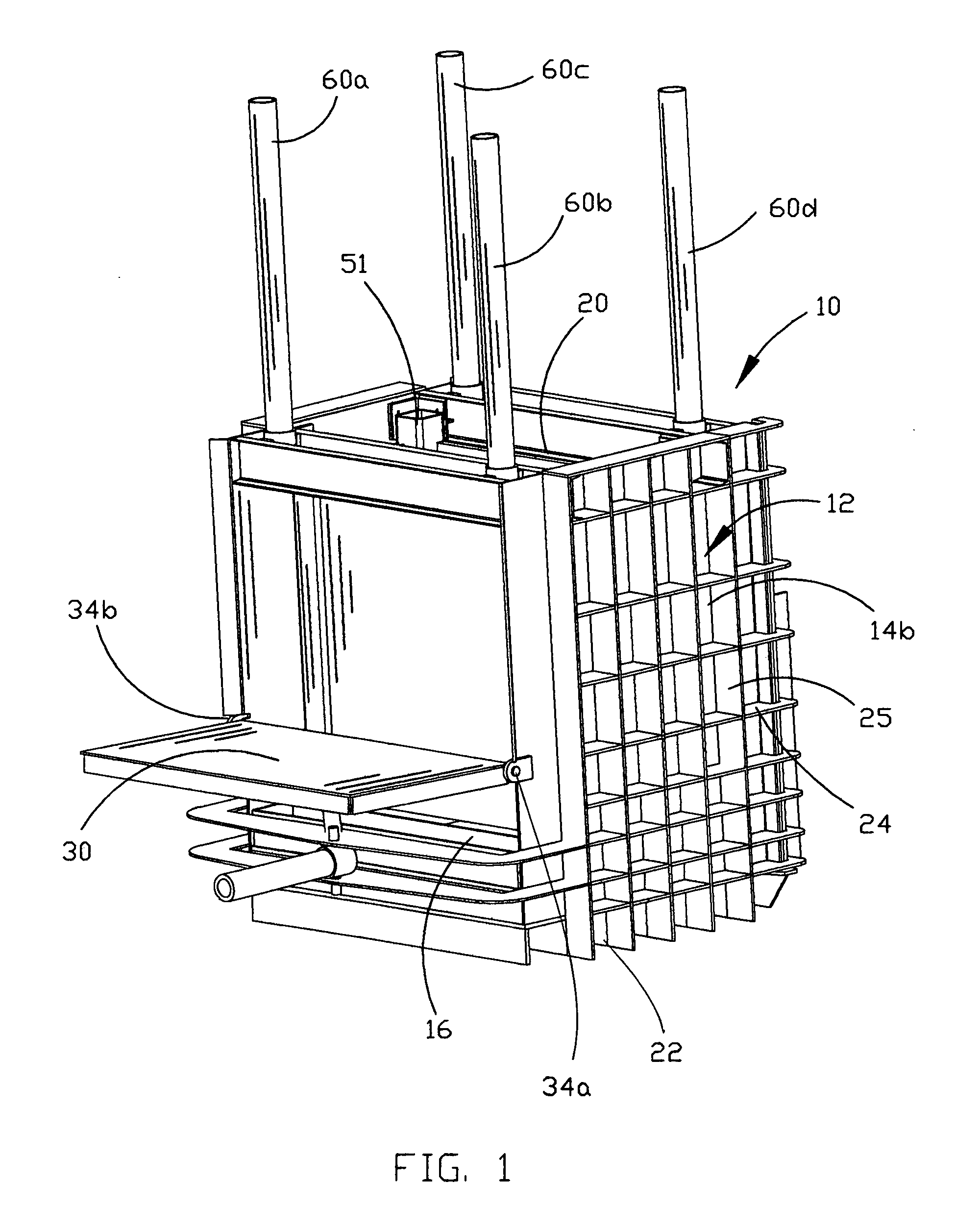
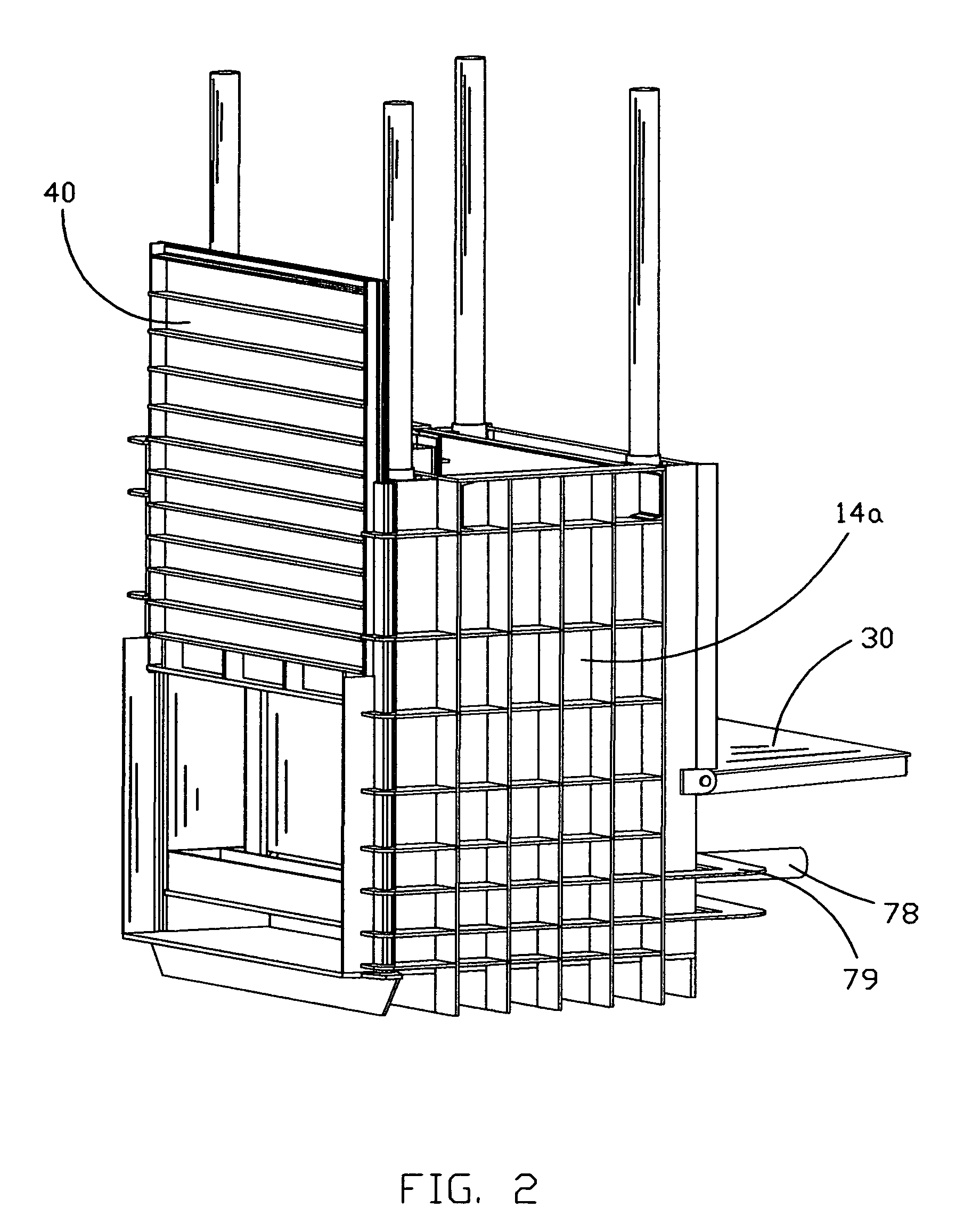
[0020]The metal crushing device 10 of the present invention is shown best in FIGS. 1-6 as including a generally rectangular box-shaped crush chamber 12 having left and right side walls 14a and 14b, a front wall 16, rear wall 18, a top wall 20, and base wall 22. In the preferred embodiment, the crush chamber 12 would have dimensions of approximately six to ten feet in height, six to ten feet in width, and six to ten feet in depth, depending on the materials with which the metal crushing device 10 is intended to be used. Also, it is expected that the crush chamber 12 will be constructed of sturdy metal panels which will resist the intense forces encountered by the walls of the crush chamber 12 when the crushing operation is being undertaken.

[0021]It is further preferred that each of the side walls 14a and 14b, front wall 16, rear wall 18, and base wall 22 be reinforced with a plurality of horizontally and vertically disposed wall strengthening ribs 24 and 25 which, in the preferred em...


PUM


Abstract

A metal crushing device includes a crush chamber having front and rear walls, side walls, a top wall and a base wall and a movable inner top wall mounted within the crush chamber and extending generally parallel with the base wall and four hydraulic cylinders mounted on the top wall and having extendable piston rods. The piston rods connect to the movable inner top wall through the top wall generally adjacent the corners thereof. Front and rear doors provide for loading and unloading of the crush chamber, and a lift device is mounted beneath the crush chamber for raising and lowering the crush chamber. An hydraulic actuator is operatively connected to the four hydraulic cylinders to extend the piston rods downwards forcing the movable inner top wall downwards to crush items within the crush chamber between the movable inner top wall and the base wall.

Description

BACKGROUND OF THE INVENTION [0001]1. Technical Field[0002]The present invention is directed to compacting and crushing devices for scrap and refuse and, more particularly, to a portable metal crushing device for crushing objects such as small appliances, car parts and the like, which includes a rectangular box-like crush chamber having a movable inner top wall, an inlet door, an outlet door, four upright hydraulic pistons mounted on top of the crush chamber for driving the movable inner top wall downwards, and a guide structure mounted atop the movable inner top wall and extending through the top wall of the crush chamber operative to guide the movable inner top wall as it moves downwards within the crush chamber to generally prevent significant shifting of the movable top wall during the crushing process.[0003]2. Description of the Prior Art[0004]There has been an almost exponential growth in the size and number of landfills being used in the United States for disposal of waste. Wh...

Claims


Application Information

Patent Timeline
IPC IPC(8): B65D5/00
CPCB30B9/3032B30B9/32B30B9/3057B30B9/3042
Inventor RAILSBACK, DAN
Owner RAILSBACK DAN
Learn More