

Piezoelectric Ceramic Composition, Method for Manufacturing the Same, and Piezoelectric Ceramic Electronic Component
a technology of piezoelectric ceramic and composition, which is applied in the field of piezoelectric ceramic electronic components, can solve the problems of insufficient increase, small improvement rate, and the inability to obtain piezoelectric ceramic composition having a sufficiently and achieves superior piezoelectric properties, high efficiency, and high piezoelectric d constant
- Summary
- Abstract
- Description
- Claims
- Application Information
AI Technical Summary
Benefits of technology
Problems solved by technology
Method used
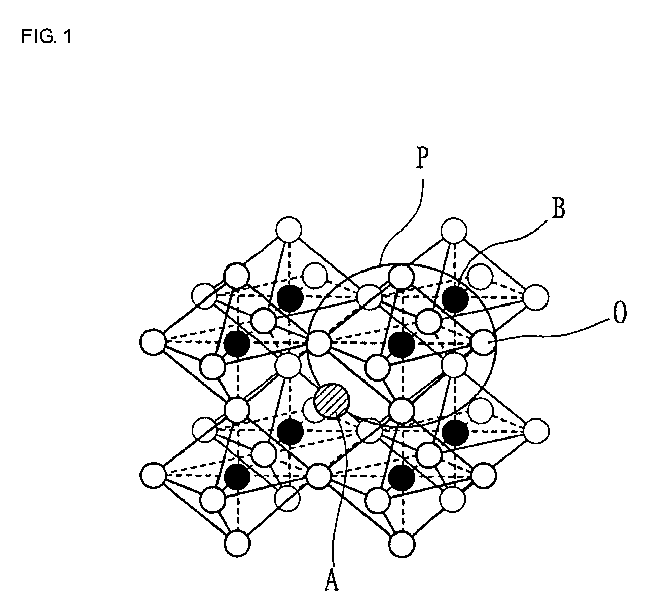
Image

Examples
example 1
[0131] As ceramic starting materials, K2CO3, Na2CO3, Nb2O5, BaCO3, CaCO3, SrCO3, TiO2, ZrO2, SnO2, In2O3, Sc2O3, Yb2O3, Y2O3, Nd2O3, Eu2O3, Gd2O3, Dy2O3, Sm2O3, Ho2O3, Er2O3, Tb4O7, Lu2O3, B2O3, and La2O3 were prepared.
[0132] Next, these ceramic starting materials were weighed so as to obtain each composition shown in Table 1 and were then charged in a ball mill, and wet mixing was performed in ethanol for approximately 18 hours. After the mixture thus obtained was dried, calcination was performed at a temperature of 700 to 1,000° C., so that a calcined product was obtained.
[0133] Next, after this calcined product was processed by coarse pulverization, an appropriate amount of an organic binder was added thereto, and wet pulverization was then performed in a ball mill for approximately 16 hours, followed by performing particle size control using a 40-mesh sieve.
[0134] Next, the powder processed by the particle size control was pressed at a pressure of 9.8×10⁷ to 1.96×10⁸ Pa for a...
example 2
[0156] As ceramic starting materials, K2CO3, Na2CO3, LiCO3, Nb2O5, Ta2O5, Sb2O5, BaCO3, TiO2, and In2O3 were prepared, and these ceramic starting materials were weighed so as to obtain each composition shown in Table 3 and were then formed into samples having Sample Nos. 31 to 53 by similar method and procedure to those of [Example 1]. In addition, the firing temperature range ΔT was also obtained in a manner similar to that of [Example 1].
[0157] Next, using the method and procedure of [Example 1], the relative dielectric constant ∈r, the electromechanical coupling factor kp, the piezoelectric d33 constant, the high electric-field piezoelectric d33 constant, and the Curie point Tc were measured.
[0158] Table 3 shows the component compositions of Sample Nos. 31 to 53, and Table 4 shows the measurement results thereof and the firing temperature ranges ΔT.
TABLE 3Composition:100{(1 − x)(K1-a-bNaaLib)m(Nb1-c-dTacSbd)O3—xBanTiO3} +SampleIn2O3NO.xabcdmn310.0050.50000.981320.10.50000.981...
example 3
[0179] As ceramic starting materials, K2CO3, Na2CO3, Nb2O5, BaCO3, TiO2, Bi2O3, ZrO2, SnO2 and In2O3 were prepared, and these ceramic starting materials were weighed so as to obtain each composition shown in Table 5 and were then formed into samples having Sample Nos. 61 to 74 by similar method and procedure to those of [Example 1]. In addition, the firing temperature range ΔT was also obtained in a manner similar to that of [Example 1].
[0180] Next, using the method and procedure of [Example 1], the relative dielectric constant ∈r, the electromechanical coupling factor kp, the piezoelectric d33 constant, the high electric-field piezoelectric d33 constant, and the Curie point Tc of Sample Nos. 61 to 74 were measured.
[0181] Table 5 shows the component compositions of Sample Nos. 61 to 74, and Table 6 shows the measurement results thereof and the firing temperature ranges ΔT.
TABLE 5Composition:100{(1 − x − y)(K0.5Na0.5)0.98NbO3-xM1M2O3−y(M30.5Bi0.5)pM4O3} +Sample(α / 2)X2O3NO.xypM1M2...
PUM
| Property | Measurement | Unit |
|---|---|---|
| molar ratio | aaaaa | aaaaa |
| specific surface area | aaaaa | aaaaa |
| particle diameter | aaaaa | aaaaa |
Abstract
Description
Claims
Application Information