
Vari-Stage Coupling Device

a coupling device and variable-stage technology, applied in the field of agricultural and horticultural, can solve the problems of reducing the flow of water, reducing the efficiency of the coupling device, and high manufacturing cos

Inactive Publication Date: 2008-03-13
AQUARIUS BRANDS +1
View PDF29 Cites 0 Cited by
  • Summary
  • Abstract
  • Description
  • Claims
  • Application Information

AI Technical Summary

Benefits of technology

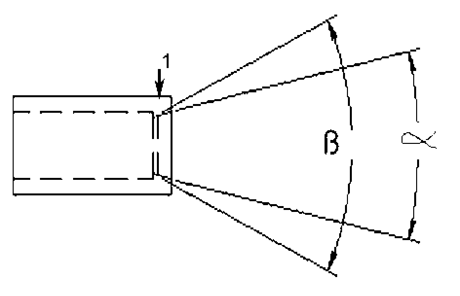
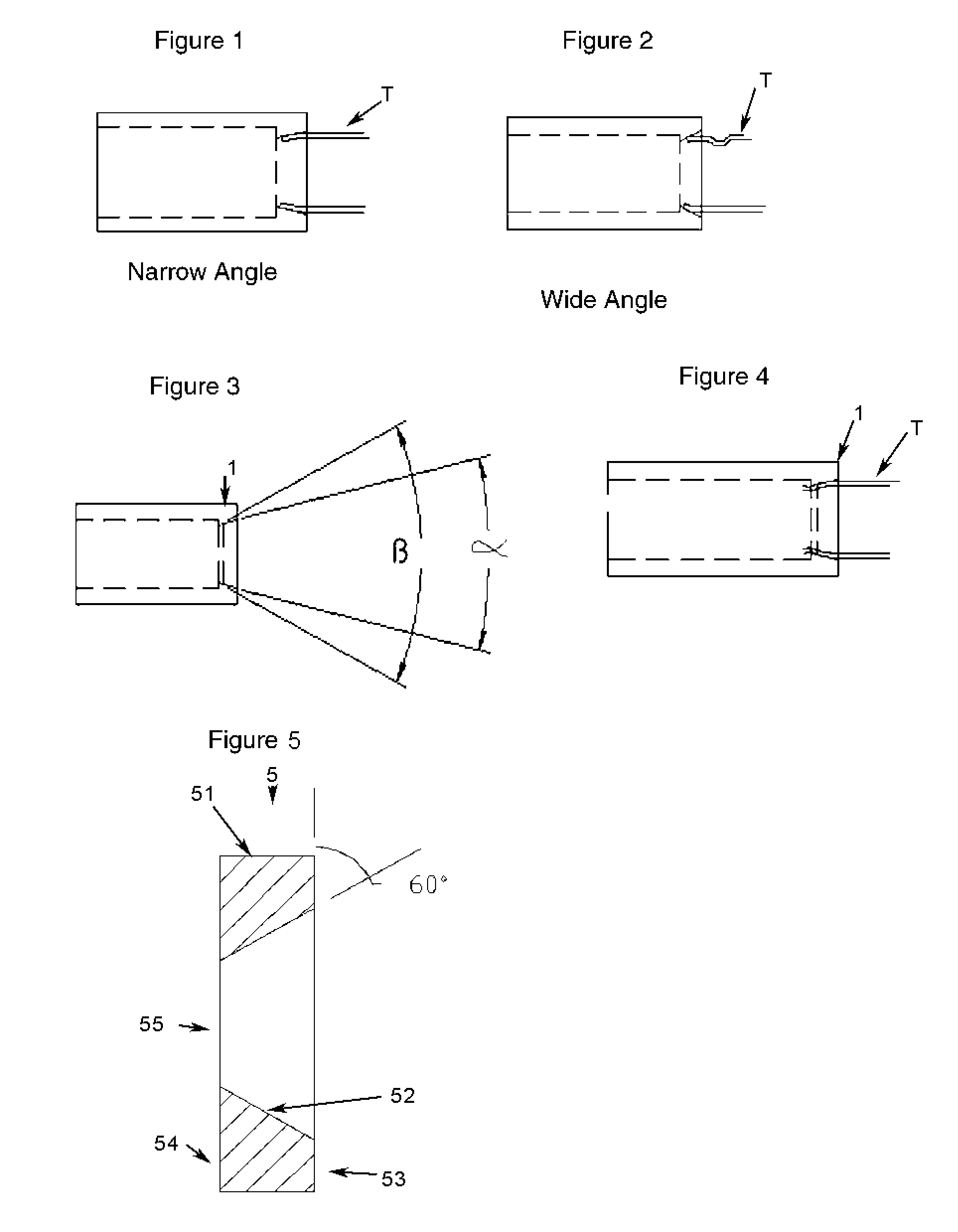
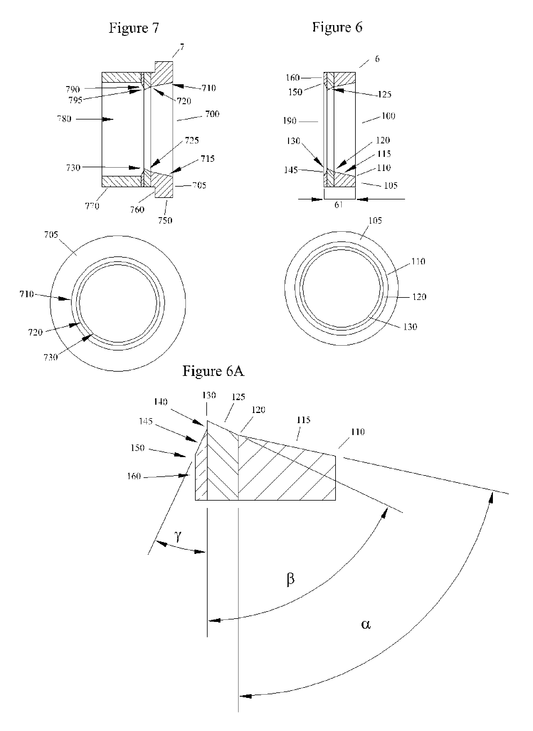
[0008]This invention consists of a dual angular barb circumferentially related about a circular opening whereby multiple sizes of irrigation tubing can be accommodate therein allowing the user the flexibility of using a single coupling to join two different sizes of tubing. The dual angular barb incorporates a narrow entry angle, about half of that of a conventional compression fitting. This allows larger diameter hoses to be swedged down, without kinking or collapsing the hose upon entry into the device. The second angle is more abrupt, about twice the angle of the entry angle but is very short in length. The termination of this second angle creates a sharp edge which incises into the inserted tubing, preventing the tubing from withdrawal from the device, absent a definite effort to do so. The swedged hose is “walked” to the second angle through a series of pushing and twisting motions into the interior of the device. When one side of the hose passes the sharp barb, it is captured and helps “walk” the hose through the opening. A reverse rake angle, immediately interiorly adjacent establishes an acute angle which creates a sharp inclination away from the diameter created by the termination of the second angle. This reverse rake also allows for a stiffening of the sharp incising edge. It should be noted that the entire tubing interface region is linearly shorter than the comparable region of prior art devices. This reduction is length allows for easier and quicker insertion of tubing into the device allowing for a less fatiguing and strenuous operation by the user. This device accommodates most tubing associated with the irrigation industry where wall thickness are generally 0.070 of an inch or less.
[0010]It is another object of this invention to create a coupling device that contains a minimal number of pieces thereby reducing manufacturing time and expense, reducing errors increasing quality and creating an inexpensive product to sell in mass quantities.
[0011]It is another object of this invention to create a coupling that has an ease of use of compression fittings decreasing the learning curve in use of the device.
[0012]It is another object of this invention is to create a device that can be used as a standalone device or in combination with other existing products to allow for use of the device in different configurations.

Problems solved by technology

In this area of application, many different manufacturers vie for a limited market and thus market fitting sizes that are unique to their tubing, forcing the user to use only their fittings onto their tubing.
In carrying water from a far away source, the tubing starts with larger diameters and due to pressure loss and friction, the flow of water decreases requiring smaller and cheaper tubing to carry the required volume of water.
But with increasing pressures, internal barbs fail to retain the tubing thereupon the barbs, developing the need for coupling devices to be used that either grab onto the end of the tubing or use the hydrostatic pressure of the water to firmly hold the tubing against a barrier preventing slippage and leakage.
The problem associated with this style of device is that it is expensive to manufacture, as unscrewing molds must be used for female threaded pieces and barbs must be fully realized in order for the device to function.
This part also has a separate external nut which can be become disassociated with the main part of the device rendering it useless.
Another disadvantage with this style of device is that flow and pressure is effected in the system as the internal barb acts as blockages to the fluid, disrupting the flow causing pressure loss.
In long tubing runs, pressure loss due to internal disruptions can be significant enough to cause additional pumps or larger pumps to be installed increasing operating costs.
The problems associated with this style of device is the cost to manufacture and eventually sell to the user.
Increasing the number of parts only increases the probably of product failure and increases the cost to the user.
The disadvantage of this device is it's inability to adapt to multiple tubing sizes.

Method used


Image

  • Vari-Stage Coupling Device
  • Vari-Stage Coupling Device
  • Vari-Stage Coupling Device

Examples


Embodiment Construction

[0025]The details of this invention is best shown in use. As an invention, there are two separate products that can be produced, a molded-in device integral with the complete unit without the possibility of separation, and as part of a separate insert, which can be used in many different applications.

[0026]FIG. 1 and FIG. 2 shows the problems associated with the prior art. When tubing T is inserted into too narrow of an angle with too long of a slope, the tubing ends are crushed which causes the outside of T to roll towards the interior of the tube T as there is a minimal amount of hoop strength associated with the style of tubing used in irrigation applications. This rolled tubing never is allowed to gain entry past the opening slope as the tubing creates an ever larger mass of rolled over tubing. FIG. 2 shows the problems associated with using too wide of an angle when tubing T is inserted thereinto. Tubing T will collapse into it's inner core as the tubing does not possess the co...


PUM

PropertyMeasurementUnit
angleaaaaaaaaaa
angleaaaaaaaaaa
angleaaaaaaaaaa

Abstract

A Vari-Stage Coupling device is discussed in this disclosure that accomplishes the goal of coupling different styles of tubing in one device. Long runs of irrigation tubing from the source of the water to the eventually dispersion contain devices that join a larger piece of tubing to a smaller piece of tubing as pressure loss degrades the flow of the water so smaller less expensive tubing is used in stages in long runs. It is also common to have a larger manifold or supply line branch off into smaller branch lines through the use of “T” fittings. It is also common to use rigid PVC tubing, which possess a smoother bore with less resistance to create a pressure drop, on long runs where flexible polyethylene or similar tubing is then attached to the end of the PVC. It would be advantageous to have a coupling device that would allow the user to incorporate different sizes of tubing into a single fitting decreasing the confusion as to which part fits with which tubing and decreasing his time looking for the right fitting. It would be advantageous for the user to need to use only one device for most all of his coupling needs. It would also be advantageous to have a coupling device that is inexpensive without the complicated nuisances of current products on market today.

Description

FIELD OF THE INVENTION [0001]This invention is designed for use in the agricultural and horticultural arenas where fluids, mainly water, is transported from a water source to the point of application using flexible conduit generally made of polymer materials. The purpose of this invention is to facilitate the coupling of two or more pieces of conduit used to join, divert or stop the flow of fluids through the conduit, whereby multiple sizes of outside diameters can be accommodated with a single device. Currently, there exists a large gap between economically feasible single size couplers and expensive and complex multi-size couplers.BACKGROUND OF THE INVENTION [0002]This invention involves the coupling of flexible tubing where the wall thickness is approximately between 10% and 25% of the total cross-sectional area of the tubing. This tubing is generally used in agricultural, horticultural and landscaping applications to serve as a conduit carrying water and fluids from a source to ...

Claims


Application Information

Patent Timeline
Patent Type & Authority Applications(United States)
IPC IPC(8): F16L37/00
CPCF16L21/002
Inventor HAWKINS, STANLEY
Owner AQUARIUS BRANDS
Learn More