Signal processing device, velocity detecting device and servo mechanism

a technology of signal processing and velocity detection, applied in the direction of electric controllers, program control, instruments, etc., can solve problems such as destabilization of control, and achieve the effect of remarkable stably controlling the control system

Inactive Publication Date: 2008-03-13
TOSHIBA MASCH CO LTD
View PDF5 Cites 8 Cited by
  • Summary
  • Abstract
  • Description
  • Claims
  • Application Information

AI Technical Summary

Benefits of technology

[0033]With this configuration, the central processing unit can control the driver applying the driving velocity information obtained by the signal processing device as the feedback signal. Consequently, the control system can remarkably stably be controlled since there is no phase-delay.

Problems solved by technology

In other words, the velocity control may have time-lag (time-delay) of ½ of a sampling cycle T. The time-lag causes phase-delay of the control system, thus destabilizing the control.

Method used


Image

  • Signal processing device, velocity detecting device and servo mechanism
  • Signal processing device, velocity detecting device and servo mechanism
  • Signal processing device, velocity detecting device and servo mechanism

Examples


first embodiment

[0045]A first embodiment of a servomechanism of the present invention will be described below.

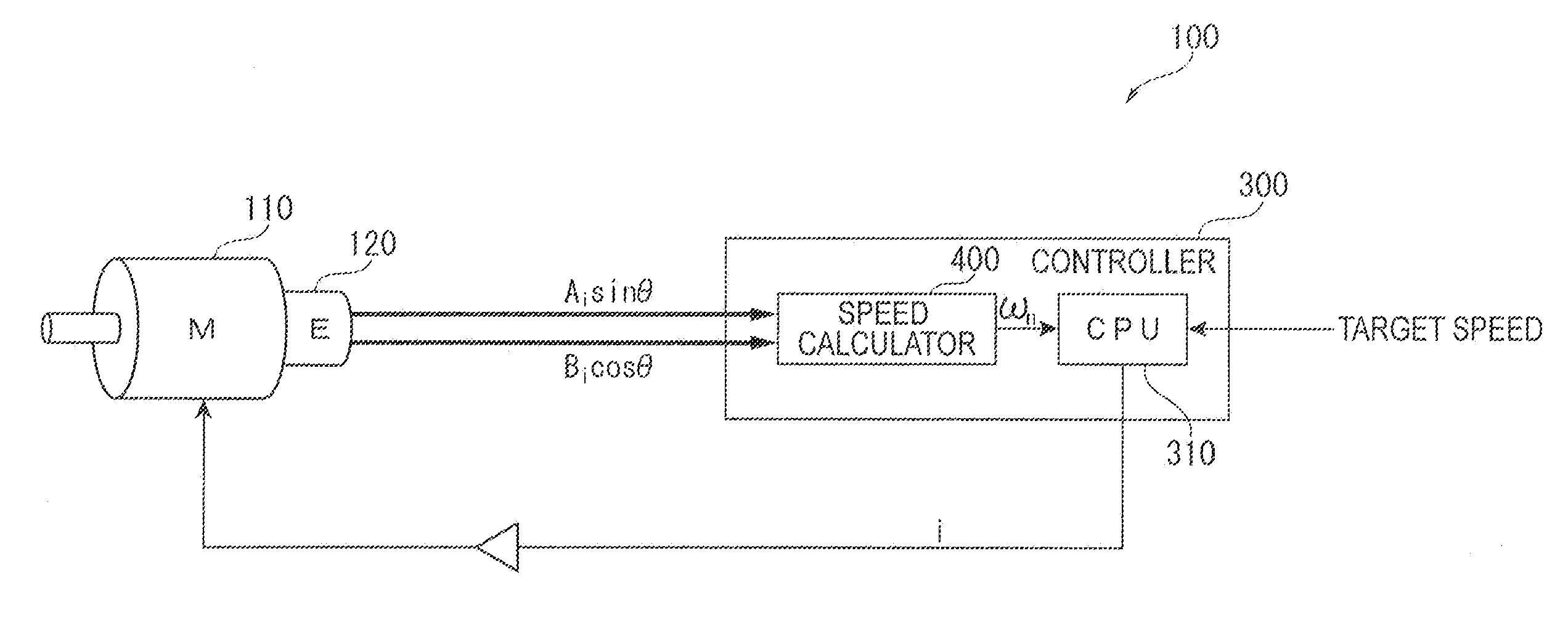
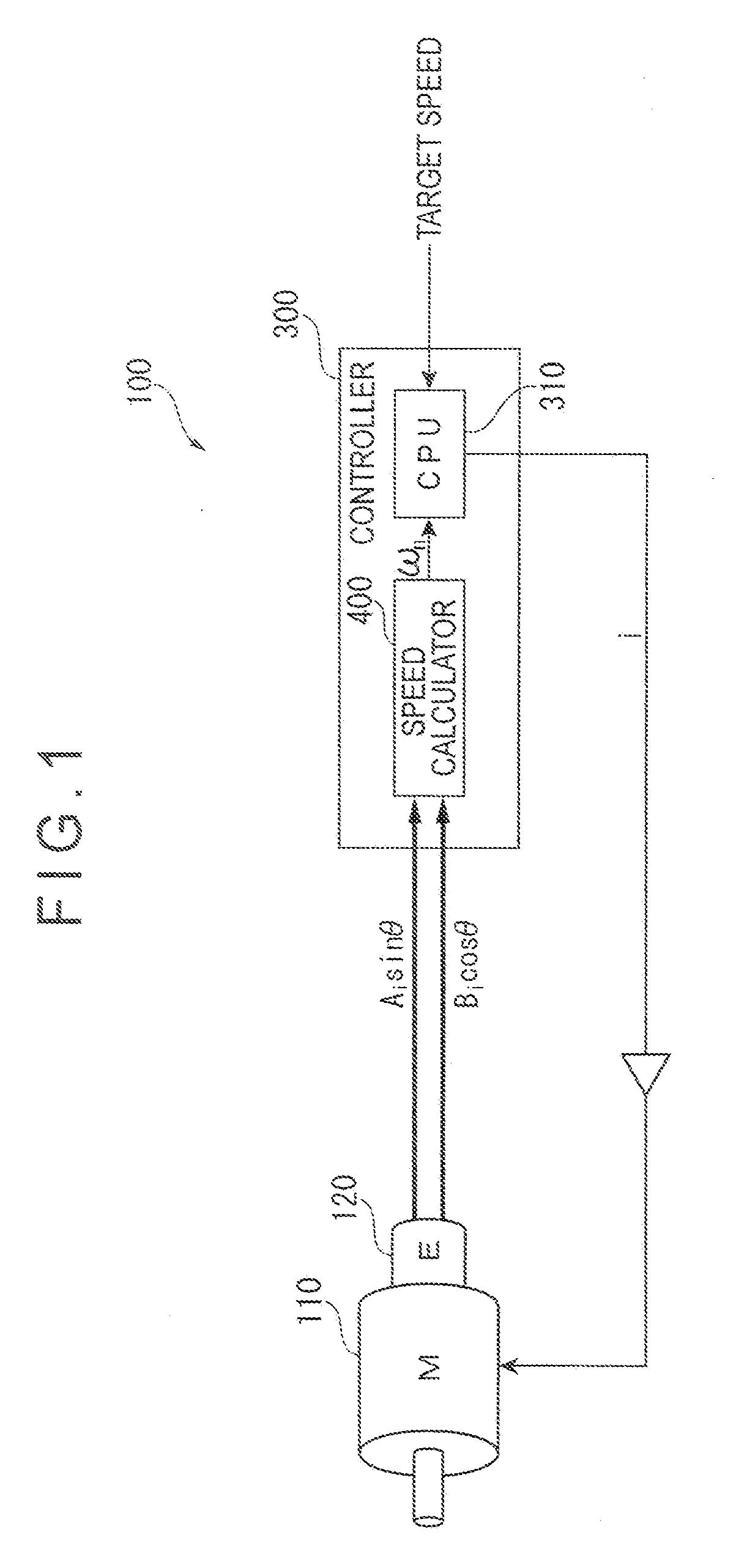
[0046]FIG. 1 is a block diagram of the servomechanism.

[0047]A servomechanism 100 includes a motor (driver) 110 as an object to be controlled, an encoder 120 as a sensor that outputs a position information signals (a periodic function signal) of both a sine wave (Asin θ) and a cosine wave (Acos θ) in accordance with rotation of the motor 110, and a controller 300 that calculates a motor rotation velocity (driving velocity information) based on the position information signal from the encoder 120 and controls the motor rotation velocity to achieve a target velocity input from the outside.

[0048]Though not described in detail, the encoder 120 is the known rotary encoder 120, which has a rotor integrally rotating with a rotator of the motor 110 and outputs the position information signal (Asin θ, Acos θ), i.e., a periodic function periodically changing in accordance with the rotation of the roto...

second embodiment

[0118]Next, a second embodiment of the present invention will be described below with reference to FIG. 6.

[0119]The basic configuration of the second embodiment is the same as the first embodiment, except for the configuration of an internal position information generator in the third embodiment.

[0120]FIG. 6 is a block, diagram showing the configuration of a velocity calculator in the second embodiment.

[0121]In FIG. 6, the internal position information generator 460 includes the first internal position information converter 463 for the sine signal processor 420, and includes the second internal position information converter 464 for the cosine signal processor 430, which is the same as the first embodiment.

[0122]Meanwhile, in the first embodiment (FIG. 3), the provision of the integrator 461 was one. When the sine signal processor 420 and the cosine signal processor 430 respectively output the motor rotation angular velocities (ω1, ω2), the signal switching section 450 selects and i...

third embodiment

[0137]Next, a third embodiment of the present invention will be described below with reference to FIG. 7.

[0138]The basic structure of the third embodiment is the same as the first embodiment, except that the motor rotation velocity is obtained based on a digital signal in which the signal from the encoder 120 is converted with an A / D converter are provided in the third embodiment.

[0139]To be more specific, in FIG. 7, a first A / D converter 710 that performs A / D conversion on the sine wave signal from, the encoder 120, and a second A / D converter 720 that performs A / D conversion on the cosine wave signal from the encoder 120.

[0140]The velocity calculator (the signal processor) 400 includes the functions of the position information signal processor, the signal switching section, the internal position information generator etc., but these functions are achieved by a predetermined signal-processing program.

[0141]Note that the present invention is not limited to the above-described, embodi...


PUM


Abstract

A driving velocity of a motor is detected by processing a position information signal output from a sensor in accordance with a driving position of a motor. The signal processing device includes a position information signal processor (410) that processes the position information signal and calculates driving velocity information of the motor, and an internal position information generator (460) that reflects a latest driving velocity information (ωn) calculated by the position information signal processor (410) and generates a latest presumed position of the motor as internal position information. An amplitude correcting unit (465) detects the amplitude of the position information signal from the sensor and corrects the amplitude of the internal position information signal based on the detected amplitude.

Description

BACKGROUND OF THE INVENTION[0001]1. Field of the Invention[0002]The present invention relates to a signal processing device, in particular, the present invention relates to a signal processing device and a velocity detecting device, each processing a two-phase signal from an encoder that detects a rotation angle of a motor and detecting a driving velocity (a rotation angular velocity) of the motor, as well as to a servomechanism controlling the driving velocity of the motor.[0003]2. Description of Related Art[0004]There has been known a servomechanism that controls a driving velocity (for instance, a relation velocity) of a motor (e.g. Document: JP-A-2004-5218).[0005]As shown in FIG. 9, a conventional servomechanism 1 includes a motor 11 (an object to be controlled), an encoder 12 that detects a rotation position (a rotation angle) of the motor 11 and outputs a position data, and a controller 13 that calculates a motor rotation velocity based on the position data from, the encoder 1...

Claims


Application Information

Patent Timeline
Patent Type & Authority Applications(United States)
IPC IPC(8): G05D13/00G01P3/44H02P29/00
CPCG05D13/62
Inventor FUJITA, JUNITO, TAKAMICHI
Owner TOSHIBA MASCH CO LTD
Why Eureka
Try Eureka