
Battery pack rechargeable by magnetic induction effect

a battery pack and magnetic induction technology, applied in the field of batteries, can solve the problems of large amount of electric current that cannot be flown through the secondary coil, difficult to make such batteries thin enough, and extremely difficult to satisfy both requirements, so as to achieve quick charge, increase current capacity, and quick charge

Inactive Publication Date: 2008-03-13
SANYO ELECTRIC CO LTD
View PDF13 Cites 44 Cited by
  • Summary
  • Abstract
  • Description
  • Claims
  • Application Information

AI Technical Summary

Benefits of technology

[0011] The above-described battery pack rechargeable by the magnetic induction effect carries the feature that, while being made thin in its entirety, a quick charge can be performed in a large amount of current. This is possible because the above-described battery pack has a flat surface of a thin battery, with a larger width than a thickness, layered with a flat coil where the wire material is spirally coiled in a flat form on the surface. The battery pack is able to increase the current capacity by enlarging a size of wire in the secondary coil in the form of the planar coil where the wire is spirally coiled. The secondary coil having a large amount of current capacity is allowed to supply high power from the first coil with a reduced heat generation while inducing the high power, so that the high power induced by the second coil is able to quickly charge the thin battery in a large amount of current, with a shorter time for charging.

Problems solved by technology

For this reason, a large amount of electric current cannot be flown through the secondary coil to quickly charge the secondary battery within a short time.
However, in a structure where a secondary coil of a metallic wire in a large gauge is incorporated within the casing and further a battery is placed inside, it is impossible to make such battery pack thin enough.
That is to say, there exists a trade-off between a quick chargeability of a battery in a large amount of current and a fabrication of a thinner battery pack, thus making it extremely difficult to satisfy the both requirements.

Method used


Image

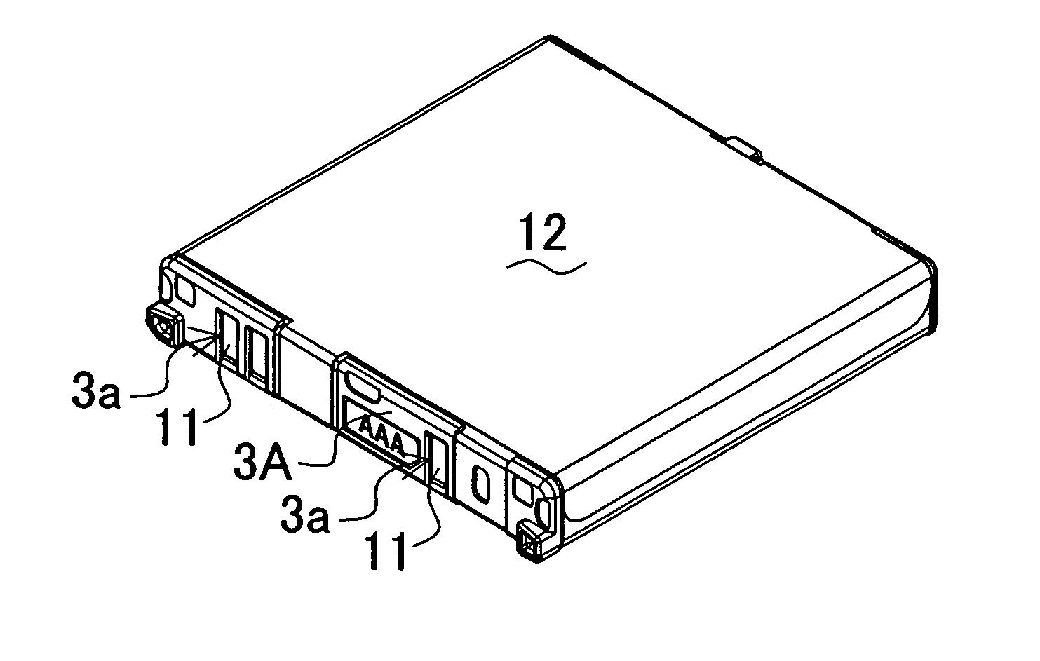
  • Battery pack rechargeable by magnetic induction effect
  • Battery pack rechargeable by magnetic induction effect
  • Battery pack rechargeable by magnetic induction effect

Examples


Embodiment Construction

)

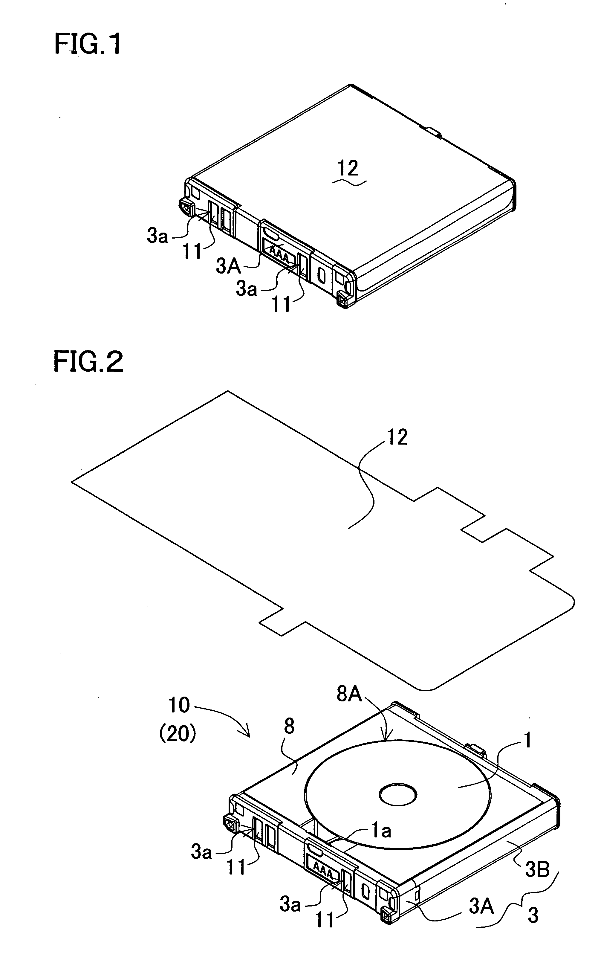
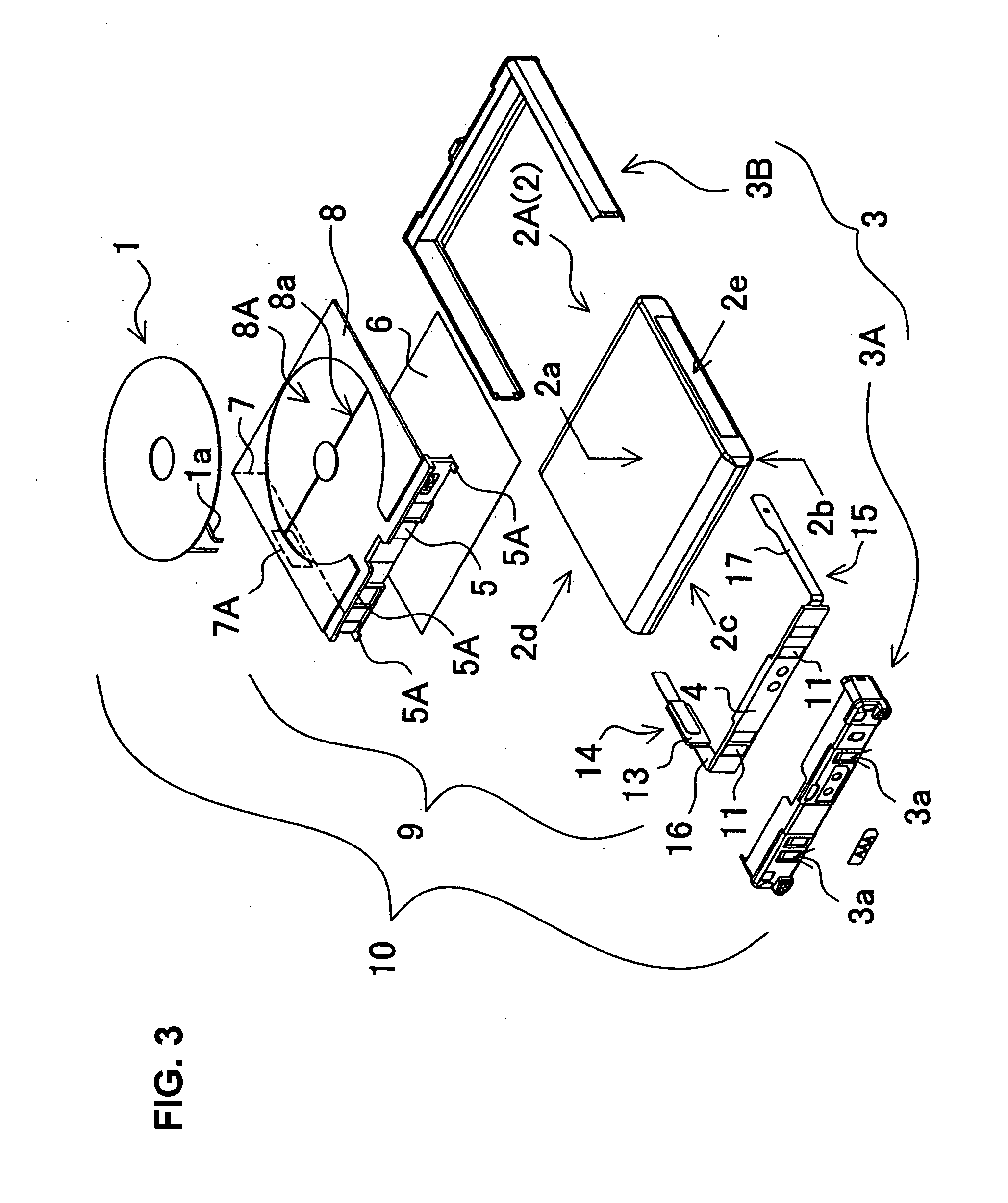
[0035] The present battery pack rechargeable by the magnetic induction effect incorporates a secondary coil 1 and a secondary battery 2. The secondary battery 2 is in a form of a thin battery 2A, and the secondary coil 1 is in a form of a planar coil.

[0036] In the present battery pack, a wire material for the secondary coil 1, 71 is made of a plurality of insulated metallic wires 19, 79, each surface of which is insulated by an insulating coating. The metallic wires are laid in a parallel relationship with respect to a first flat surface 2a of the thin battery 2A, and are made into the form of the planar coil being spirally coiled. Further, the plurality of insulated metallic wires 19, 79 being disposed in such a parallel relationship and spirally coiled can be electrically connected in parallel.

[0037] In the present battery pack, the wire material for the secondary coil 81 is an insulated metallic wire 88, each surface of which is insulated by an insulating coating. Further, the...


PUM


Abstract

A battery pack rechargeable by a magnetic induction effect incorporates a secondary coil electromagnetically coupled to a primary coil of a battery charger and a secondary battery rechargeable by electric power induced to the secondary coil. The secondary battery is in a form of a thin battery having a larger width than a thickness, and two opposing surfaces of the secondary battery are composed of a first flat surface and a second flat surface. The secondary coil is in a form of a planar coil with a wire material being spirally coiled in the plane. In the battery pack, the secondary coil in the form of the planar coil is fixedly layered on the first flat surface of the thin battery.

Description

BACKGROUND OF THE INVENTION [0001] 1. Field of the Invention [0002] The present invention relates to a battery pack which is rechargeable by a magnetic induction effect. [0003] 2. Description of the Related Art [0004] A battery pack rechargeable by a magnetic induction effect is charged by using a contactless battery charger. The battery packs where a battery is rechargeable in such a method are disclosed in Japanese Laid-Open Patent Publication No. H09-063655 (1997) and Japanese Laid-Open Utility Model Publication No. S58-021968 (1983). The battery pack described in Japanese Laid-Open Patent Publication No. H09-063655 (1997) has a secondary coil disposed within its casing. The secondary coil, being provided in a flexible circuit board, is disposed inside the casing. [0005] The battery pack described in Japanese Laid-Open Utility Model Publication No. S58-021968 (1983) has a secondary coil fixed, in a layered state, to the bottom of a tubular battery. The battery pack thus structure...

Claims


Application Information

Patent Timeline
Patent Type & Authority Applications(United States)
IPC IPC(8): H02J7/00
CPCH02J7/0045H02J7/025H01M10/44H01M10/052H01M2/1061Y02E60/10H02J50/10
Inventor TOYA, SHOICHIINOUE, YASUSHIMATSUDA, TAKUYA
Owner SANYO ELECTRIC CO LTD
Learn More