
Apparatus and methods for demodulating a signal

a modulated signal and apparatus technology, applied in the field of apparatus and methods for demodulating a modulated signal, can solve the problems of inherently complex inclusion of vco or nco, radio frequency (rf) front end of the receiver requires automatic gain control (agc), and typically consumes a large amount of power

Active Publication Date: 2008-03-13
WIPRO LTD
View PDF1 Cites 23 Cited by
  • Summary
  • Abstract
  • Description
  • Claims
  • Application Information

AI Technical Summary

Benefits of technology

The present invention provides apparatus and methods for demodulating signals that have been modulated according to various modulation schemes, such as pi / 4DQPSK, pi / 2DBPSK, GMSK, and GFSK. The apparatus includes a hard limiter stage, a digital down converter and low pass filter stage, a symbol synchronization stage, an instantaneous phase detector stage, a fine frequency offset compensation stage, a phase offset compensation stage, and a demapper stage. The methods involve receiving an analogue input signal, converting it to a two level signal, applying a discrete Fourier transform process to extract symbol timing, calculating the instantaneous phase of the symbols, applying a frequency compensation signal to compensate for the effects of frequency offset, and estimating the residual frequency offset to update the frequency offset compensation signal. The apparatus and methods can be used for demodulating signals in various communication systems.

Problems solved by technology

One drawback of this arrangement is that analogue-to-digital conversion typically consumes a large amount of power.
Another drawback is that the Radio Frequency (RF) front end of the receiver requires Automatic Gain Control (AGC).
A further disadvantage is that the inclusion of a VCO or an NCO is inherently complex, requiring large and expensive circuit configurations.
Furthermore, there are a number of other disadvantages in the above-mentioned methods which use a hard limiter, and these include a serious performance degradation relative to other conventional methods in which an analogue to digital conversion takes place.
Also, these methods are primarily used for dealing with pi / 4 DQPSK modulation which uses little power and is insensitive to the nonlinearity in the RF components.

Method used


Image

  • Apparatus and methods for demodulating a signal
  • Apparatus and methods for demodulating a signal
  • Apparatus and methods for demodulating a signal

Examples


Embodiment Construction

[0039]The preferred embodiment of the present invention will be described in detail by way of following examples and with reference to the above-mentioned figures.

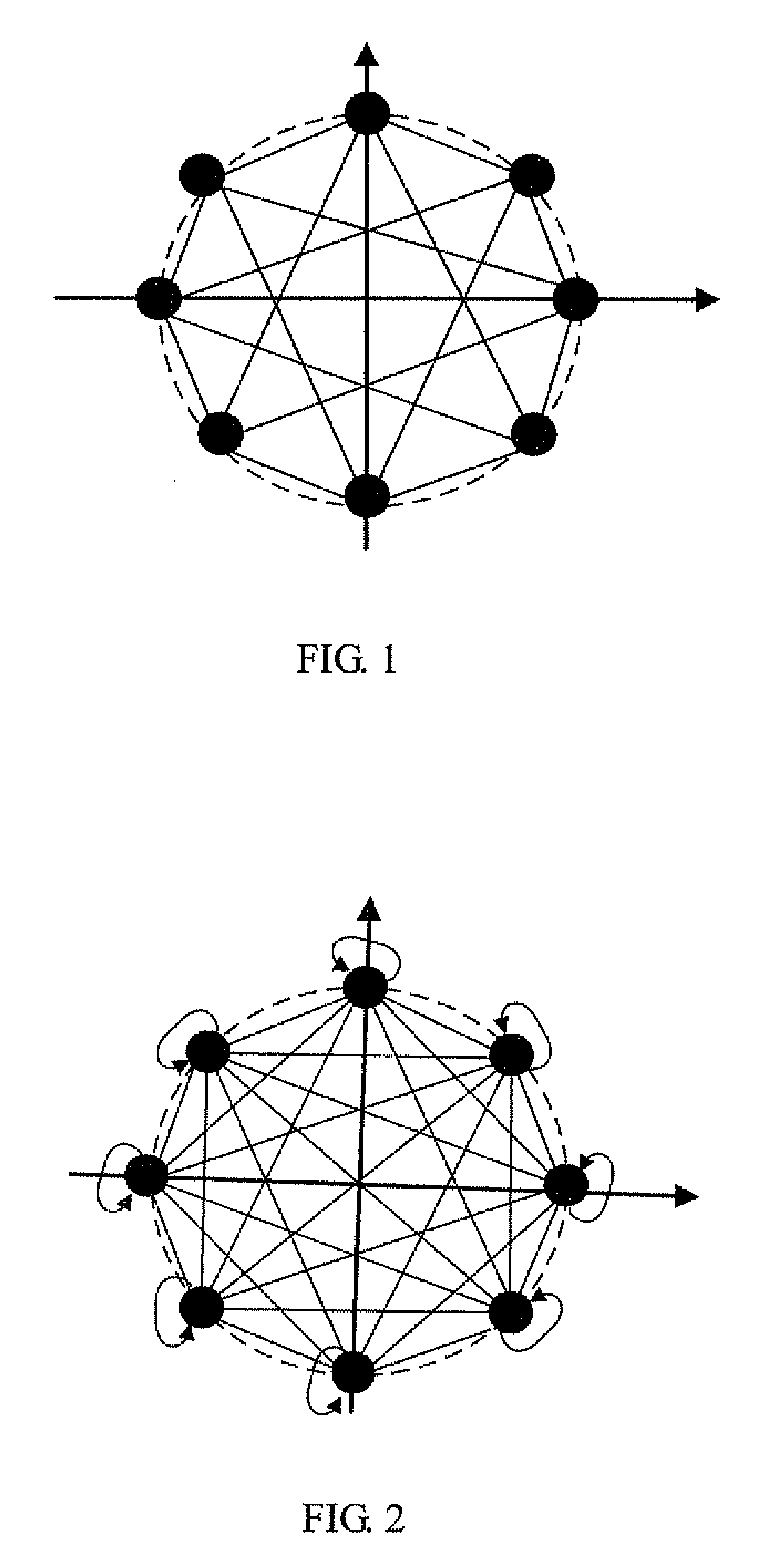
[0040]FIG. 1 and FIG. 2 are schematic diagrams showing respectively a pi / 4 DQPSK constellation for a modulation system in which the signal does not pass through the origin and a D8QPSK constellation for a modulation system in which the signal may pass through the origin. One or more preferred embodiments of the present invention is arranged to demodulate signals modulated according to one or other or both of the modulation systems illustrated in FIG. 1 and FIG. 2.

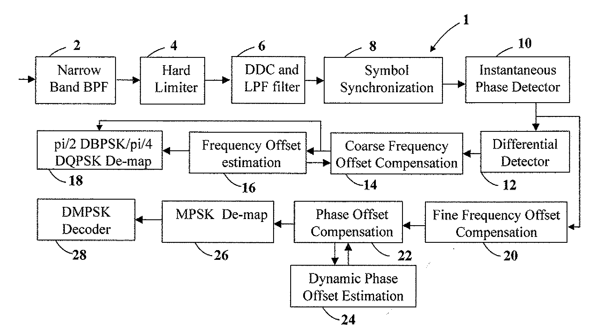
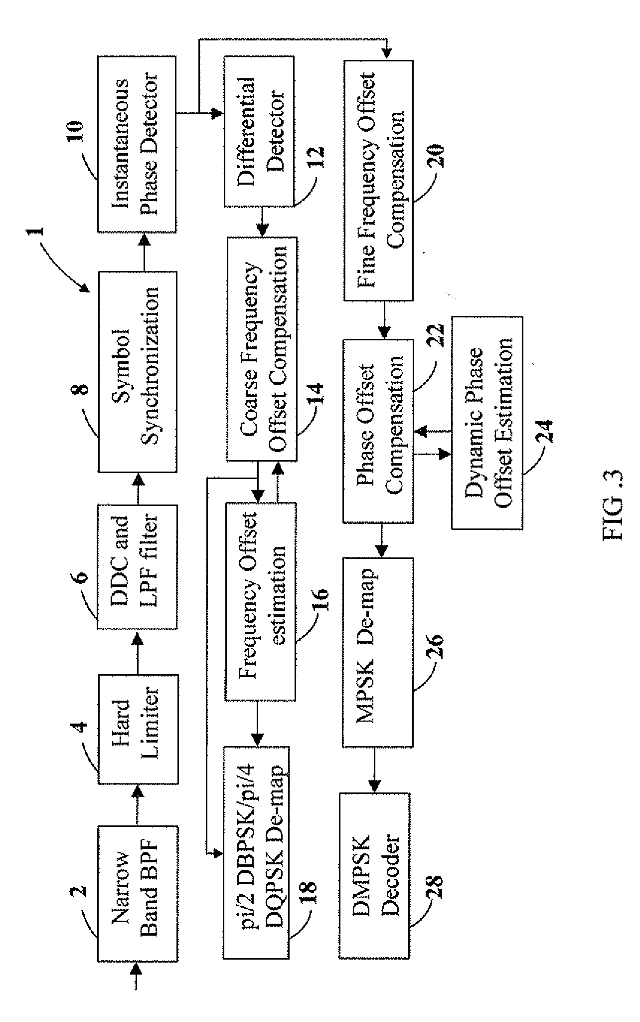
[0041]FIG. 3 shows an apparatus 1 according to a preferred embodiment of the present invention. In the apparatus 1, an incoming signal is applied to a narrow band pass filter 2 and the output of the filter 2 is applied to a hard limiter stage 4. The hard limiter stage 4 converts the incoming analogue signal to a two-level signal. The output IF signal of the hard l...


PUM


Abstract

An apparatus for demodulating an analogue input signal comprises a hard limiter stage (4) for converting the signal to a two level signal, A digital down converter / low pass filter stage (6) converts the signal to a base band signal, and a symbol synchronization stage (8) extracts symbol timing. An instantaneous phase detector (10) calculates the instantaneous phase of the one or more symbols associated with the input signal. If the input signal has been modulated according to a pi / 4DQPSK, pi / 2DBPSK, GMSK, or a GFSK modulation scheme, a differential detector (12) determines a difference in the phase between adjacent symbols, a coarse frequency offset compensation stage (14) applies a compensation signal to compensate for frequency offset, and a frequency offset estimation stage (16) updates this compensation signal. A demapper (18) generates a demodulated output signal after compensation by the frequency offset compensation stage.

Description

BACKGROUND OF THE INVENTION[0001]1. Field of the Invention[0002]The present invention relates to apparatus and methods for demodulating a modulated signal, for example, according to one or more of a π(pi) / 4 differential quaternary phase shift keying (DQPSK) modulation scheme, a pi / 2 differential-binary phase-shift keying (DBPSK) modulation scheme, a Gaussian minimum shift keying (GMSK) modulation scheme, a Gaussian Frequency-Shift Keying (GFSK) modulation scheme, a Differential M-ary Phase Shift Keying (DMPSK) modulation scheme or an M-ary Phase Shift Keying (MPSK) modulation scheme.[0003]2. Description of Related Art[0004]M-ary Phase Shift Keying (MPSK) and Differential M-ary Phase Shift Keying (DMPSK) are widely used in wireless communication and satellite communication. In MPSK modulation scheme, the phase of the current symbol is switched among M values according to the modulated binary input signal to be transmitted. In DMPSK modulation scheme, the difference between the phase ...

Claims


Application Information

Patent Timeline
Patent Type & Authority Applications(United States)
IPC IPC(8): H04L27/22
CPCH04L27/0014H04L27/22H04L2027/0026H04L27/233H04L27/2275
Inventor TINGWU, WANGYAN, PAN JUYANG, YUSAIGUI, HUMASAYUKI, TOMISAWA
Owner WIPRO LTD
Learn More