Radio ranging using sequential time-difference-of-arrival estimation

a time-difference of arrival and ranging technology, applied in the field of radio communication systems, can solve the problems of fading, interference, frequency selectivity, and processing does not account for the phenomenon of fading, and achieve the effect of reducing errors

Inactive Publication Date: 2008-03-13
MITSUBISHI ELECTRIC RES LAB INC
View PDF3 Cites 41 Cited by
  • Summary
  • Abstract
  • Description
  • Claims
  • Application Information

AI Technical Summary

Benefits of technology

[0014]According to embodiments of the invention, time-domain windowing is used to perform threshold-based sequential TDOA estimation. The invention reduces errors due to multipath and non-line-sight propagation and noise-noise cross-terms.

Problems solved by technology

The main problem with passive radar is that the relative timing of pulses in the received signals is unknown.
However, that processing does not account for the phenomena of fading, frequency selectivity, interference, nonlinearity, terrain blocking and dispersion.
Therefore, the performance can degrade significantly in multipath environments, and in the presence of non-white noise, as is frequently the case in terrestrial channels.
Although the GCC filtering techniques can improve TDOA estimation, they are ineffective for multipath propagation, which causes correlated noise in the received signals.
However, those techniques can also fail when there are more than three multipath components.
One problem with the conventional cross-correlation processing is that if the time interval T for the cross-correlation is not selected appropriately, i.e., longer than needed, extra noise can be accumulated.
In addition, in the presence of multipath propagation, multiple cross-correlation peaks can occur, which can increase the estimation error significantly.

Method used


Image

  • Radio ranging using sequential time-difference-of-arrival estimation
  • Radio ranging using sequential time-difference-of-arrival estimation
  • Radio ranging using sequential time-difference-of-arrival estimation

Examples


Embodiment Construction

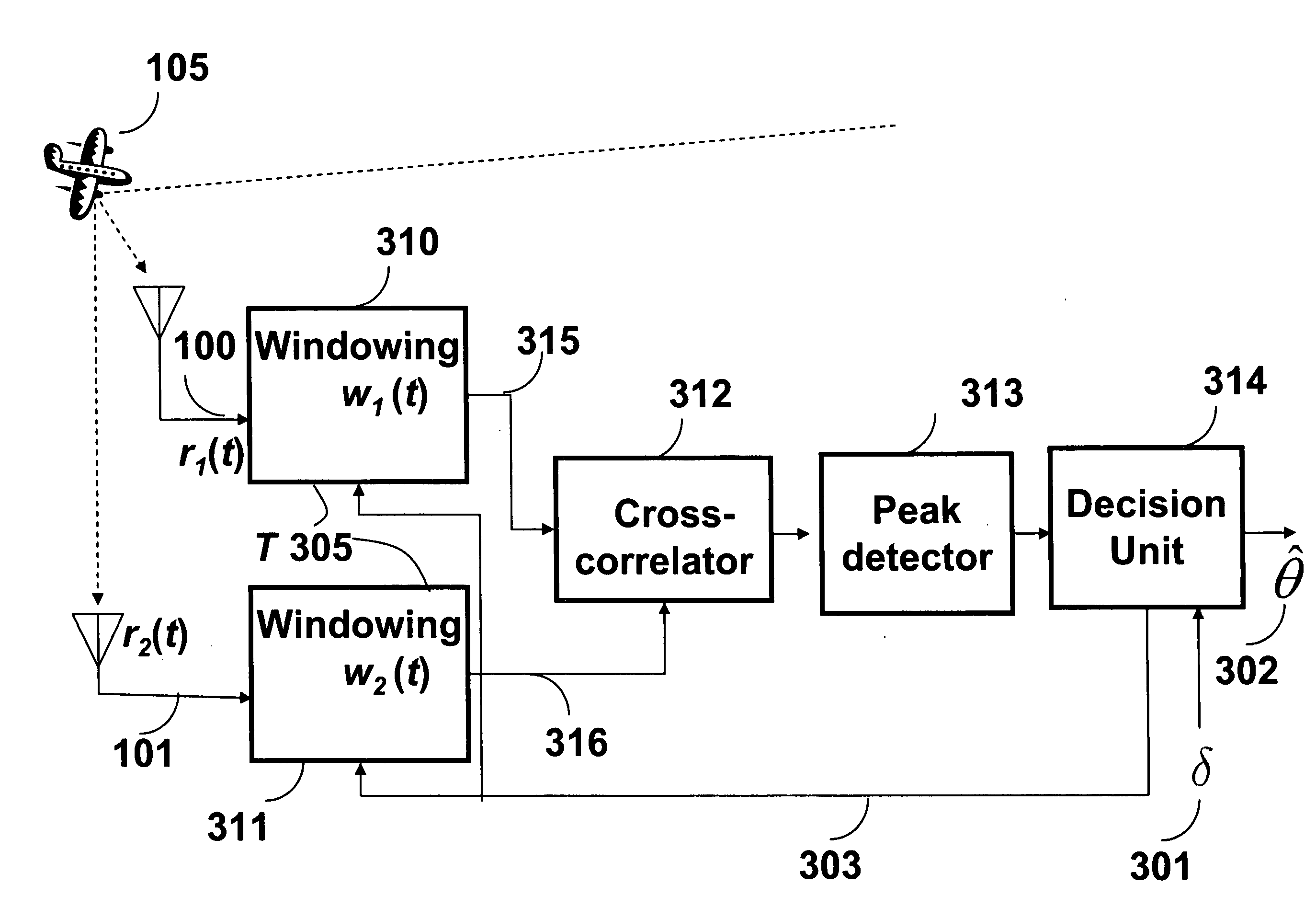
[0022]The embodiments of our invention provide a method and system for determining a position of a target objects by measuring time delays between pairs of radio signals received from the target object by passive sensors.

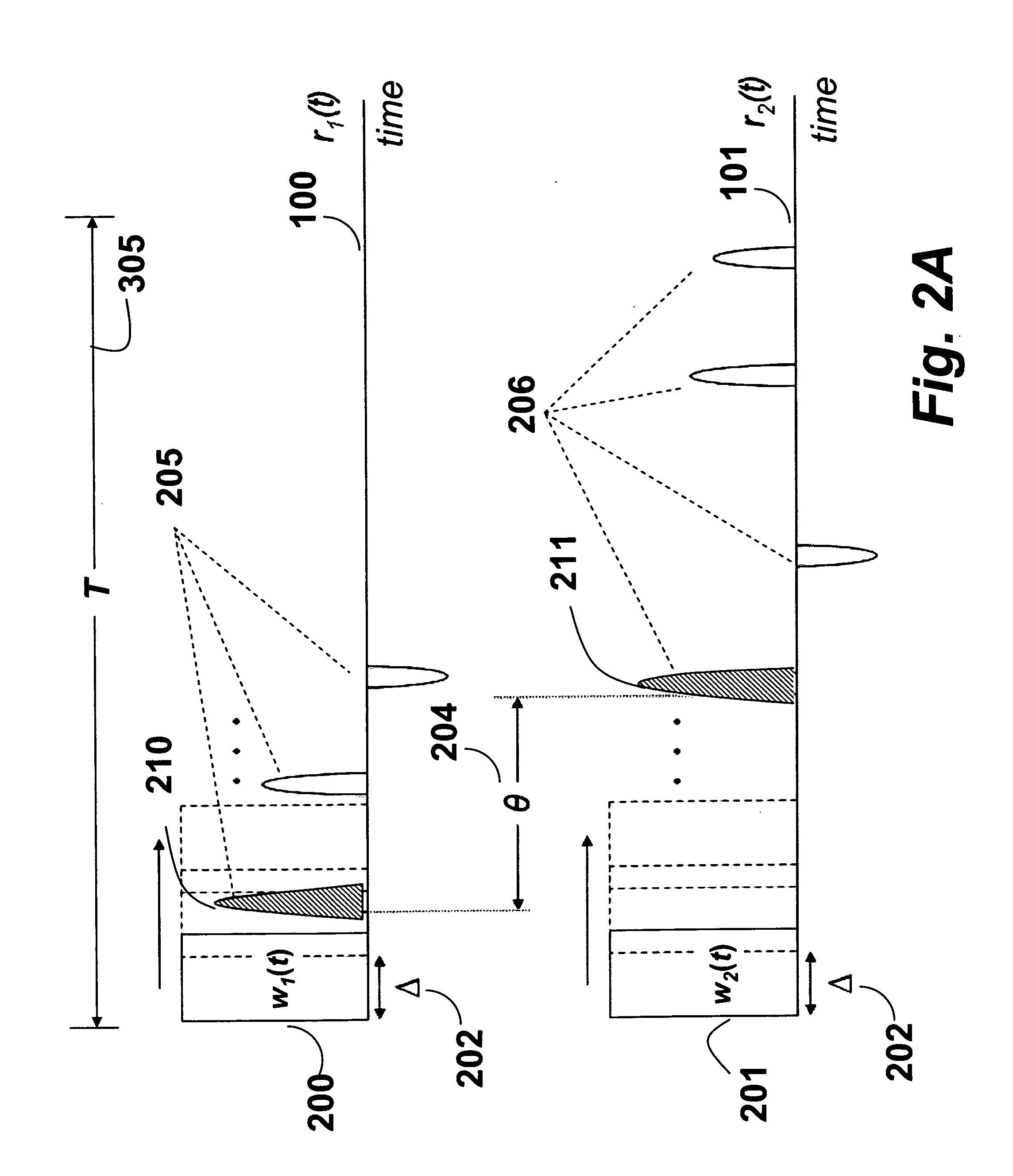
[0023]As shown in FIGS. 2A-2B and 3, we repeatedly apply 310-311 time-domain window functions w1(t) 200 and w2(t) 201 to a pair of received signals, a first signal r1(t) 100 and a second signal r2(t) 101 to produce windowed signals, 315-316. FIG. 2B shows the cross-correlations 250 for the first and last window positions in a correlation time interval 305. Typically, the window functions are identical and the correlation time interval 305 is shorter than the time between successive transmitted pulses.

[0024]As known in the art, and in contrast with filters used in conventional TDOA systems, a window function or an apodization function performs a multiplication in the time domain. The window function is zero-valued outside of the window interval. For instance, a windo...


PUM


Abstract

A method determines a position of a target object. A window function is applied repeatedly to a first signal and a second signal of a pair of radio signals received at a pair of passive sensors from a target object while time shifting the window function during a correlation interval to produce a first windowed signal and a second windowed signal for each application. The first windowed signals are cross-correlating with the second windowed signals to determine a peak for each cross-correlation. The peaks are compared sequentially in time with a predetermined threshold to detect a first pulse in the first signal and a first pulse in the second signal. A delay between the first pulses indicative of a position of the target object.

Description

FIELD OF THE INVENTION [0001]The present invention relates generally to radio communication systems, and more particularly to radio ranging and a determining a position of a target object by measuring time differences between pairs of radio signals received from the target object.BACKGROUND OF THE INVENTION [0002]In a passive radar system, radio signals reflected or transmitted by a target object are received by multiple passive sensors geographically distributed. Passive sensors do not emit the radio signals that are reflected, as would be the case in an active radar system. The main problem with passive radar is that the relative timing of pulses in the received signals is unknown.[0003]Usually, the passive sensors forward the received radio signals to a centralized processing unit. The processing unit performs a cross-correlation on pairs of signals to estimate a time-difference-of-arrival (TDOA) for pairs of the signals. The TDOA can then be used to determine the position of the...

Claims


Application Information

Patent Timeline
Patent Type & Authority Applications(United States)
IPC IPC(8): G01S1/24
CPCG01S5/0215G01S5/0221G01S13/878G01S13/003G01S5/10G01S5/02213G01S5/0218
Inventor GEZICI, SINANSAHINOGLU, ZAFERZHANG, JINYUN
Owner MITSUBISHI ELECTRIC RES LAB INC
Why Eureka
Try Eureka