Optical coordinate input device comprising few elements

a technology of optical coordinate input and input device, which is applied in the field of optical input system, can solve the problems of not being able to use a simple object, not having moving parts such as mirrors,

Inactive Publication Date: 2008-03-13
BARUCH ITZHAK
View PDF8 Cites 103 Cited by
  • Summary
  • Abstract
  • Description
  • Claims
  • Application Information

AI Technical Summary

Benefits of technology

[0057]The present invention provides an optical unit for an object coordinates determination by using minimal number of components, this unit can be realized with only one unit, in contrast to prior art device types which are usually comprised of few units or use a special object to be used as a pointing device. In addition, the preset invention requires only basic optical elements such as a photo sensing unit, lenses, light source, filter or shutters thus, it can be manufactured for low cost.
[0058]Minimal optical parts are used in order to achieve the simplicity of the optical device. In one of the embodiment, one unit that is mounted on the corner of the computer screen monitors the area immediately in front of the screen, the main advantage of this embodiment is the fact that it can be comprised of one photo- sensing device in a relatively small unit. Additional advantage over units presented in prior art is the fact that majority of the suggested embodiments can be installed in close proximity to a screen display corner while operating at a large viewing angle, thus saving valuable space for the user while increasing the usability of such device.
[0062]Further, the coordinate input apparatus in accordance with the present invention can be provided with additional lenses or photo sensing devices in order to enable large viewing-angle, thus it enables immediate attachment of such device near its measurement space. Such large viewing angle is created by placing the lenses and the photo sensing devices in specific locations and angles.
[0064]Electronic shutters may be used in order to separate the images reflected on the photo sensing device surface, two methods are possible for reducing the number of such shutters. The first method depends on the physical dimensions of the various system components. The other method is based on operation of electronic means in order to subtract one image from the other, thus revealing both images that are necessary for a triangulation calculation.

Problems solved by technology

One disadvantage of such scanning system is the need to have moving parts such as a mirror.
The usage of such system is limited because of the special pen circuit; it is not possible to use a simple object such as a regular pen or a human finger to operate the device.
The main disadvantage of these two last patents is the fact that two units are needed in each system.
Another disadvantage is the fact that in the first patent a wide-angle lens system is needed, and in the second patent only a limited viewing angle is possible thus, the units of such system need to be installed with some distance from a screen display frame.

Method used


Image

  • Optical coordinate input device comprising few elements
  • Optical coordinate input device comprising few elements
  • Optical coordinate input device comprising few elements

Examples


Embodiment Construction

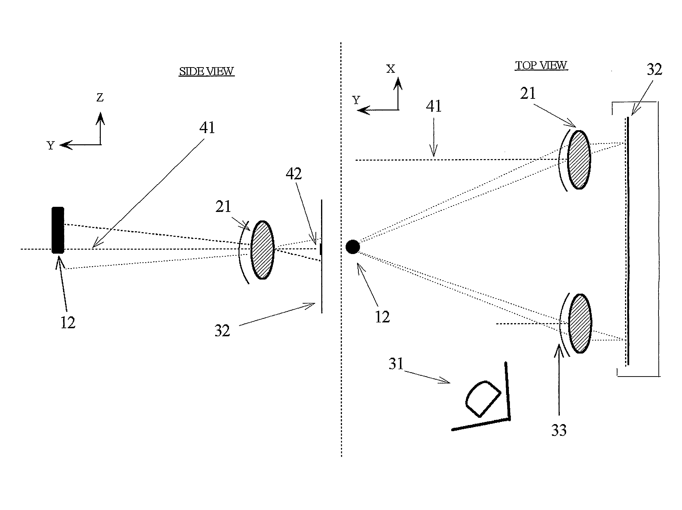
[0069]The main feature of the present invention is the use of a one-unit device having a simple optical configuration that is capable of finding the coordinates of an arbitrary object within a wide viewing angle.

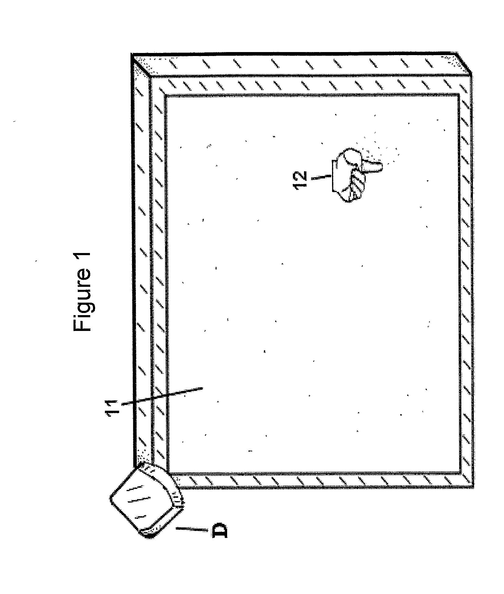
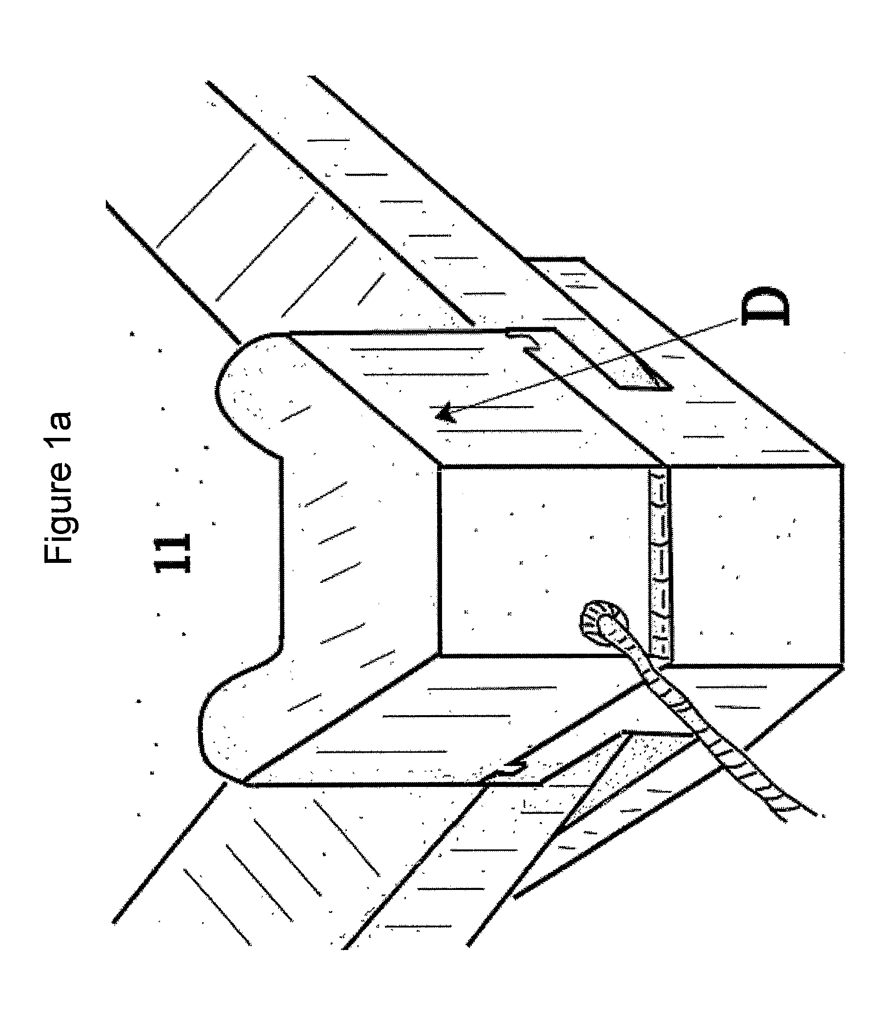
[0070]In several of the preferred embodiments described in the present invention, a rectangular measurement area is presented while the device is placed near one of the corners of the measurement area. The methods described here enable placement of the device relatively close to such corners enabling practical installation on a display frame while consuming minimal space at a lower cost than two-unit configurations.

[0071]In other preferred embodiments described in the present invention, a three-dimensional image representation may be obtained by using a simple optical configuration. The use of such embodiments may relate to places were a limited space is available while three-dimensional information is needed from objects placed relatively in close range to the device.

[0072]...


PUM


Abstract

The present invention is an optical electronic input device for identifying the coordinates of an object in a given area. The device may capture two-dimensional or three-dimensional input information, using a minimal number of optical units (one for two dimensional coordinates and two for three dimensional coordinates). The invention requires only basic optical elements such as a photo sensing unit, lenses, a light source, filters and shutters which may reduce manufacturing costs significantly. Since this device enables inputting the coordinates of an object in a set area, it may not only be used in systems such as optical touch screens, but also in virtual keyboard applications and in implementation for machine vision.

Description

FIELD OF THE INVENTION[0001]The present invention relates to an optical input system for measuring an object's three-dimensional coordinates, with a special reference made to the light receiving unit wherein a number of optical elements are being used in combination with photo sensing devices. The invention enables usage of one input unit with minimal sensing devices while increasing the viewing angle of such input devices. Furthermore, the present invention relates to usage of such systems in applications or computer coordination input devices such as an optical touch screen, virtual keyboard applications, and implementation for machine vision.BACKGROUND[0002]Various systems are known in the art for detecting an object coordinates. Some of such systems are touch screens and blackboard inputting devices. These systems usually detect coordinates of a pointing instrument such as a pen, a fingertip or a special device designed for use with such system.[0003]Among the methods of operati...

Claims


Application Information

Patent Timeline
Patent Type & Authority Applications(United States)
IPC IPC(8): G06F3/042G01B11/14G09G5/08
CPCG06F3/0421
Inventor BARUK, ITZHAK
Owner BARUCH ITZHAK
Why Eureka
Try Eureka