Electrical device cooling structure in vehicle

a technology of electric devices and cooling structures, which is applied in the direction of hybrid vehicles, cell components, primary cell maintainance/servicing, etc., can solve the problems of increasing the size of the power supply device to impose a limitation on mounting the power supply device on the vehicle, and not disclose the cooling of the dc/dc converter and the motor driving inverter included in the power supply device, so as to prevent an increase in the size of the electrical device, the effect of enhancing cooling performan

Inactive Publication Date: 2008-03-13
HONDA MOTOR CO LTD
View PDF12 Cites 68 Cited by
  • Summary
  • Abstract
  • Description
  • Claims
  • Application Information

AI Technical Summary

Benefits of technology

[0009]The present invention has been achieved in view of the above-described circumstances, and has an object to enhance cooling performance for an electrical

Problems solved by technology

Japanese Patent Application Laid-open No. 2003-45392 discloses that the battery of the power supply device is cooled by the cooling air supplied by the forced air fan, but does not disclose cooling of a DC/DC converter and a motor driving inverter included in the power supply device.
Therefore, even if the battery on an upstream side can be sufficiently cooled, there is a possibility that the motor driving inverter on a dow

Method used


Image

  • Electrical device cooling structure in vehicle
  • Electrical device cooling structure in vehicle
  • Electrical device cooling structure in vehicle

Examples


Embodiment Construction

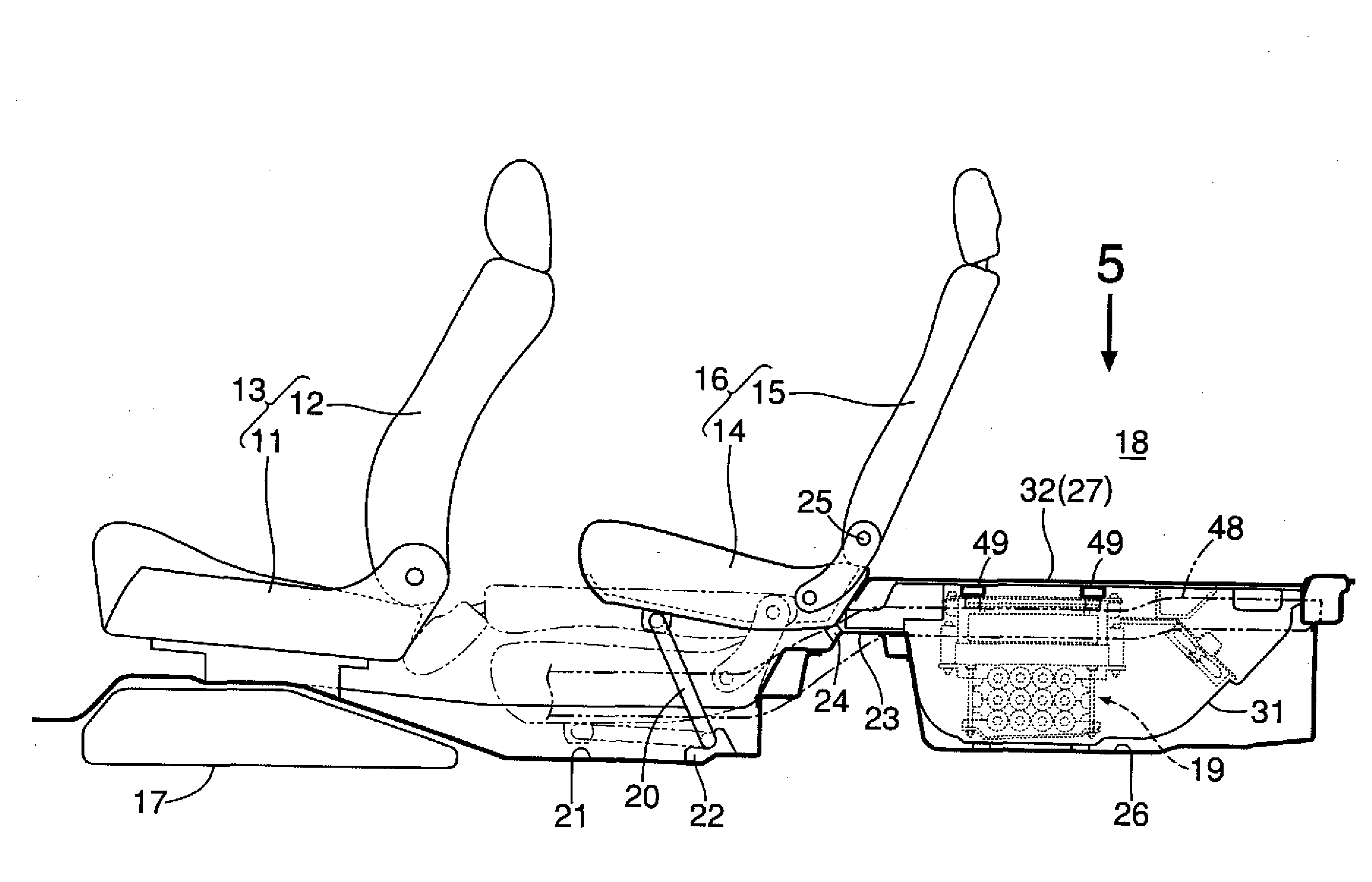
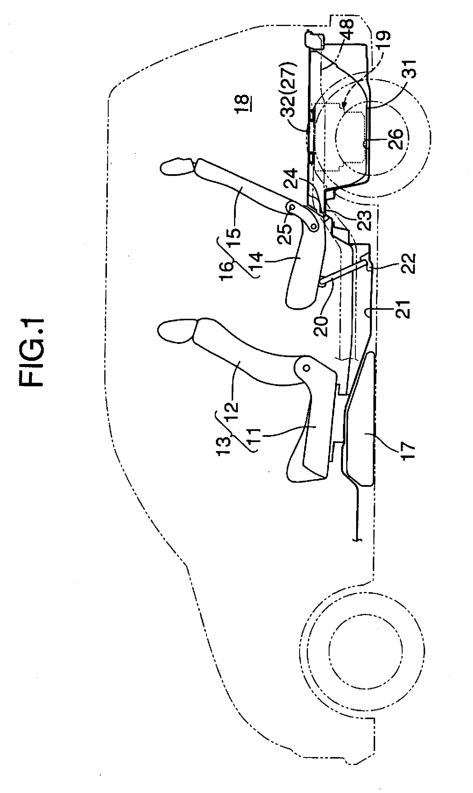
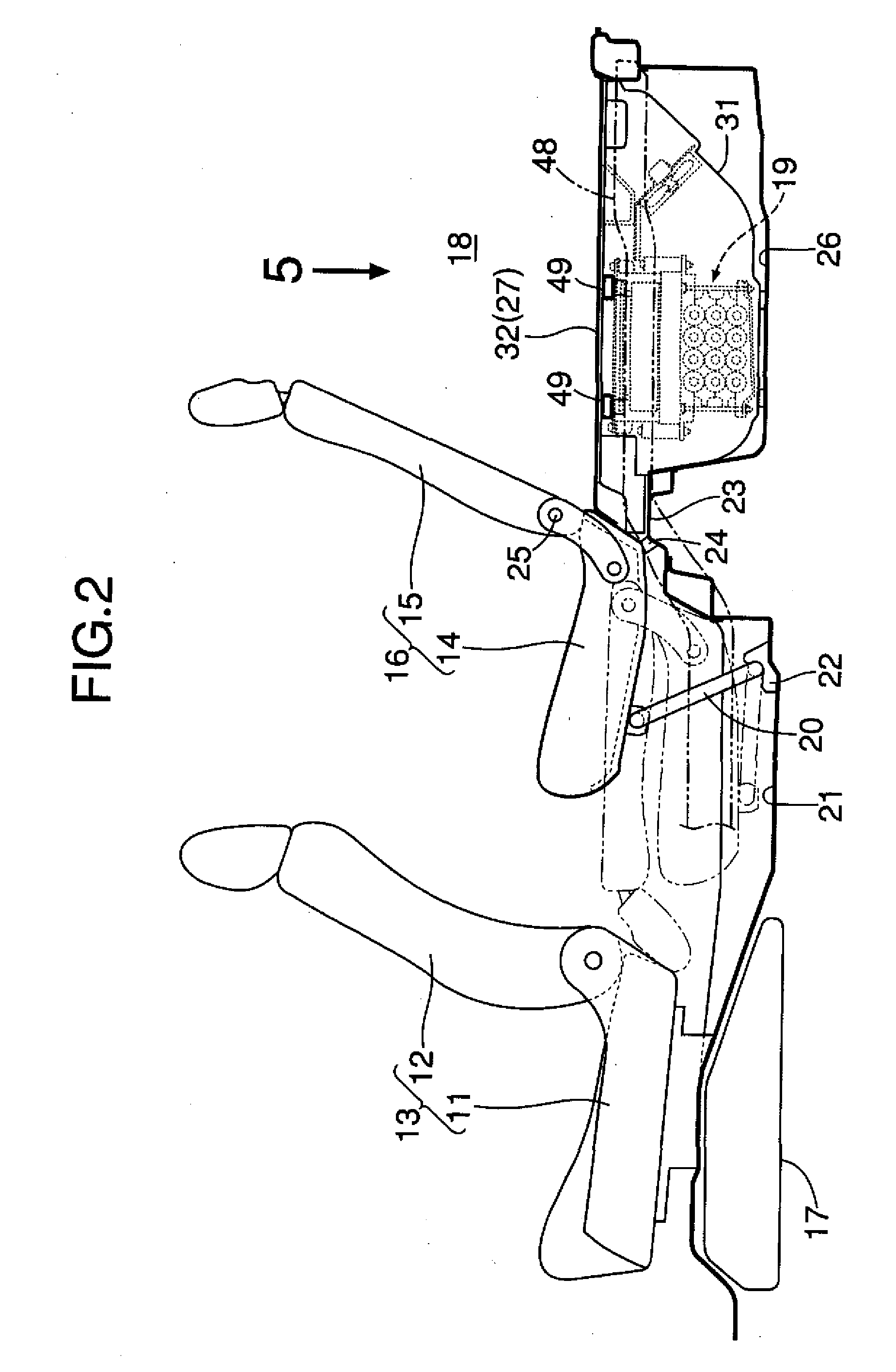
[0035]As shown in FIGS. 1 and 2, a hybrid vehicle has an engine and a motor, which are not shown, as a drive source for traveling. The hybrid vehicle comprises: a front seat 13 including a seat cushion 11 and a seat back 12; and a rear seat 16 including a seat cushion 14 and a seat back 15. A fuel tank 17 is disposed below the seat cushion 11 of the front seat 13. A power supply unit 19 for driving the motor is mounted below a luggage space 18 behind the rear seat 16.

[0036]A pair of right and left stays 20 and 20 are foldably provided on a lower surface of the seat cushion 14 of the rear seat 16. In a use state of the rear seat 16, the rear seat 16 is fixed as follows: lower ends of the stays 20 and 20 are locked to hooks 22 and 22 provided on an under-seat floor 21 of the rear seat 16; and a rear end of the seat cushion 14 is locked to a seat cushion locking portion 24 provided on a bulging portion 23 in the rear of the under-seat floor 21. The seat back 15 can be tilted forward on...


PUM


Abstract

In a power supply unit disposed below a floor behind a seat, battery modules are disposed in a lower position, and a DC/DC converter and a motor driving inverter are disposed side by side in a vehicle width direction above the battery modules. Thus, cooling air flowing from the front side to the rear side of a vehicle body is divided into upper and lower portions to cool in parallel the DC/DC converter 41 and the motor driving inverter on the upper side and the battery modules on the lower side. Thus, it is possible to simplify a passage of the cooling air to reduce the size of the entire power supply unit, and improve mountability of the power supply unit on the vehicle body. Also, it is possible to apply cooling air at low temperature before heat exchange to all the battery module, the DC/DC converter, and the motor driving inverter, thereby enhancing cooling effect.

Description

BACKGROUND OF THE INVENTION[0001]1. Field of the Invention[0002]The present invention relates to an electrical device cooling structure in a vehicle, comprising: an electrical device which includes a battery for driving a motor for traveling, a DC / DC converter and a motor driving inverter, the electrical device being disposed below a floor behind a seat, and cooled by cooling air.[0003]2. Description of the Related Art[0004]Japanese Patent Application Laid-open No. 2003-45392 discloses a device in which a power supply device including a battery that drives a motor for traveling of an automobile is mounted in a trunk room behind a rear seat, and the battery is cooled by cooling air supplied by a forced air fan provided integrally with the power supply device.[0005]Japanese Patent Application Laid-open No. 2005-153827 discloses a device in which a capacitor including a battery that drives a motor for traveling of an automobile, a DC / DC converter, a motor driving inverter, a cooling fa...

Claims


Application Information

Patent Timeline
IPC IPC(8): H05K7/20H01M50/202H01M50/224H01M50/249
CPCB60K1/04H05K7/20909B60K2001/0416H01M2/1077H01M6/5038H01M10/5004H01M10/5016H01M10/503H01M10/5067H01M10/5073Y10S903/903Y02T10/7005Y02T10/705Y02T10/7241Y02T10/7233B60L1/003B60L11/1874B60L11/1877B60L11/1879B60L2210/12B60L2210/40B60L2240/525B60L2270/147B60K2001/005H01M10/625H01M10/6563H01M10/643H01M10/6566H01M10/613B60L58/26B60L50/66B60L50/64Y02T10/70Y02T10/72Y02E60/10H01M50/249H01M50/224H01M50/202
Inventor FUKAZU, TOMOHIRONISHIBORI, TAKEOSHIBUYA, KENTAROKAWATA, MASAOYAMAGUCHI, HIROOFUJISAWA, JUNYANAKANO, ATSUSHIKOSAKA, HIROSHI
Owner HONDA MOTOR CO LTD
Why Eureka
Try Eureka