

Radio Communication Device and Radio Communication Method
a radio communication and radio communication technology, applied in the direction of transmission path division, multi-frequency code system, transmission path sub-channel allocation, etc., can solve the problems of significant attenuation due to transmission distance and increase in number, and achieve the effect of suppressing an increase in power consumption
- Summary
- Abstract
- Description
- Claims
- Application Information
AI Technical Summary
Benefits of technology
Problems solved by technology
Method used
Image

Examples
embodiment 1
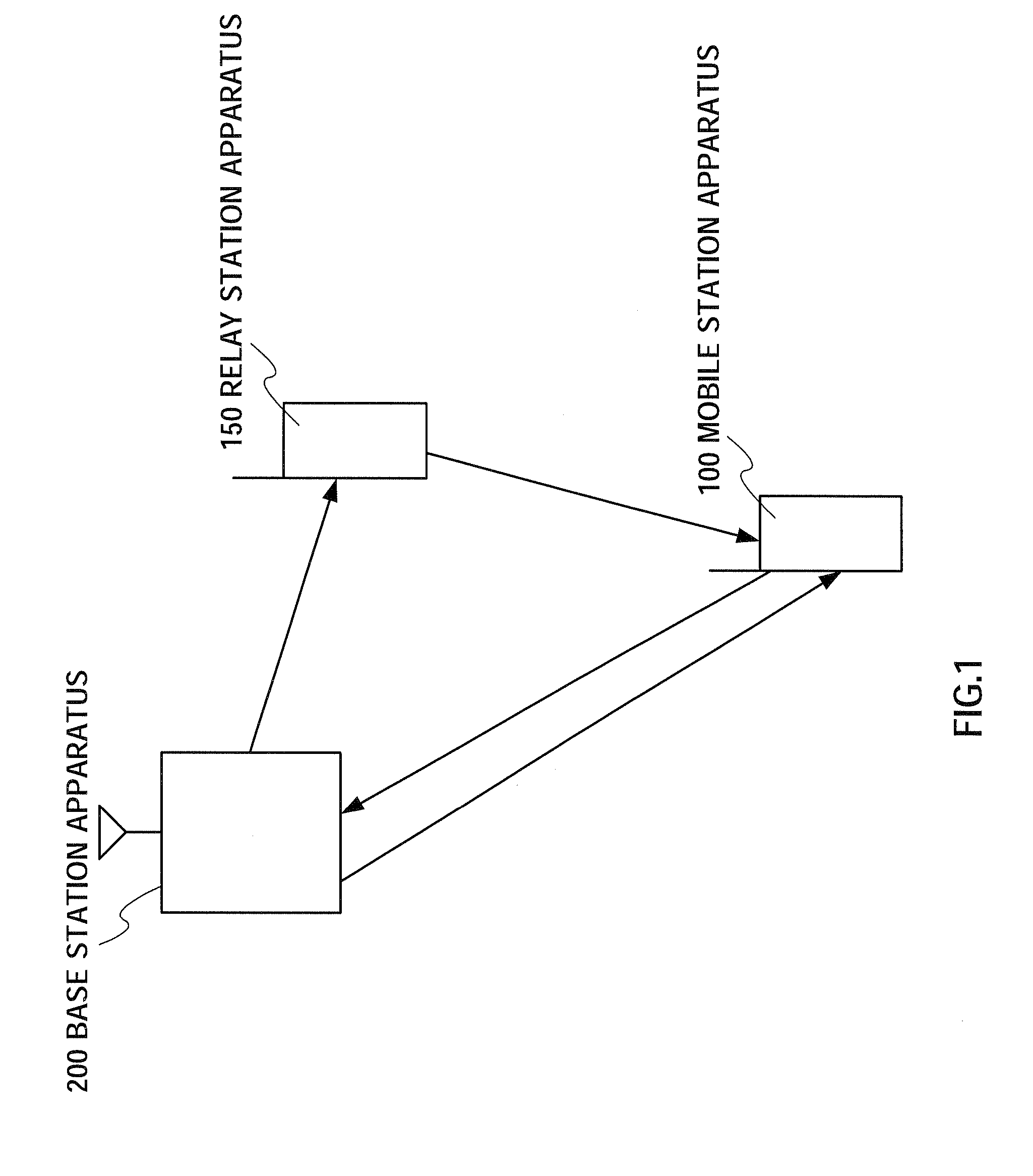
[0054] As shown in FIG. 1, the mobile communication system according to the present embodiment is comprised of a mobile station apparatus 100, a relay station apparatus 150 and a base station apparatus 200.
[0055] Base station apparatus 200 instructs in advance relay station apparatus 150 to relay a signal to mobile station apparatus 100. Also, base station apparatus 200 holds corresponding information of the identification information for mobile station apparatus 100 and relay station apparatus 150, and relay station apparatus 150 holds identification information of mobile station apparatus 100, which is the object of relaying. Also, the identification information of relay station apparatus 150 may also be held in mobile station apparatus 100.
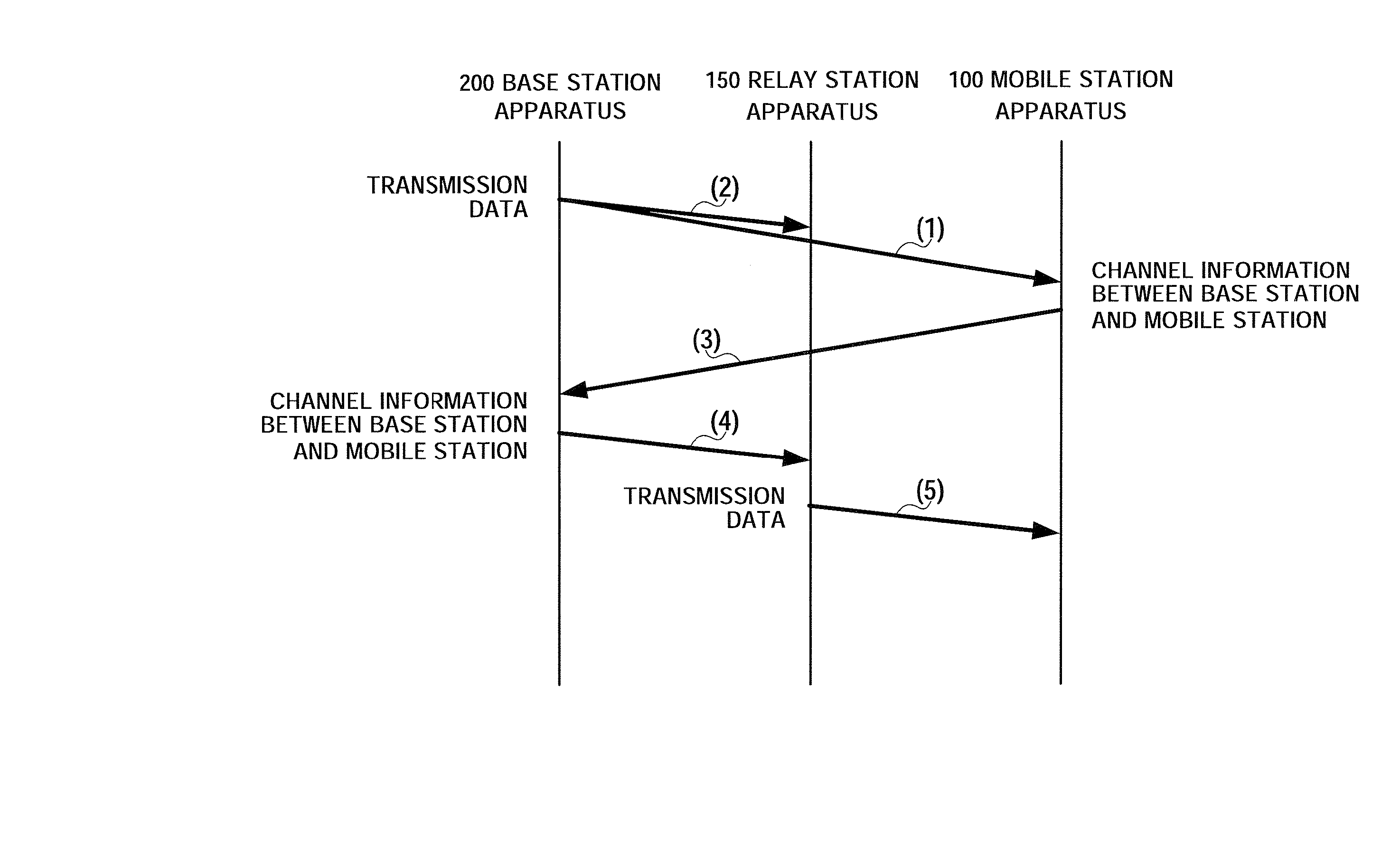
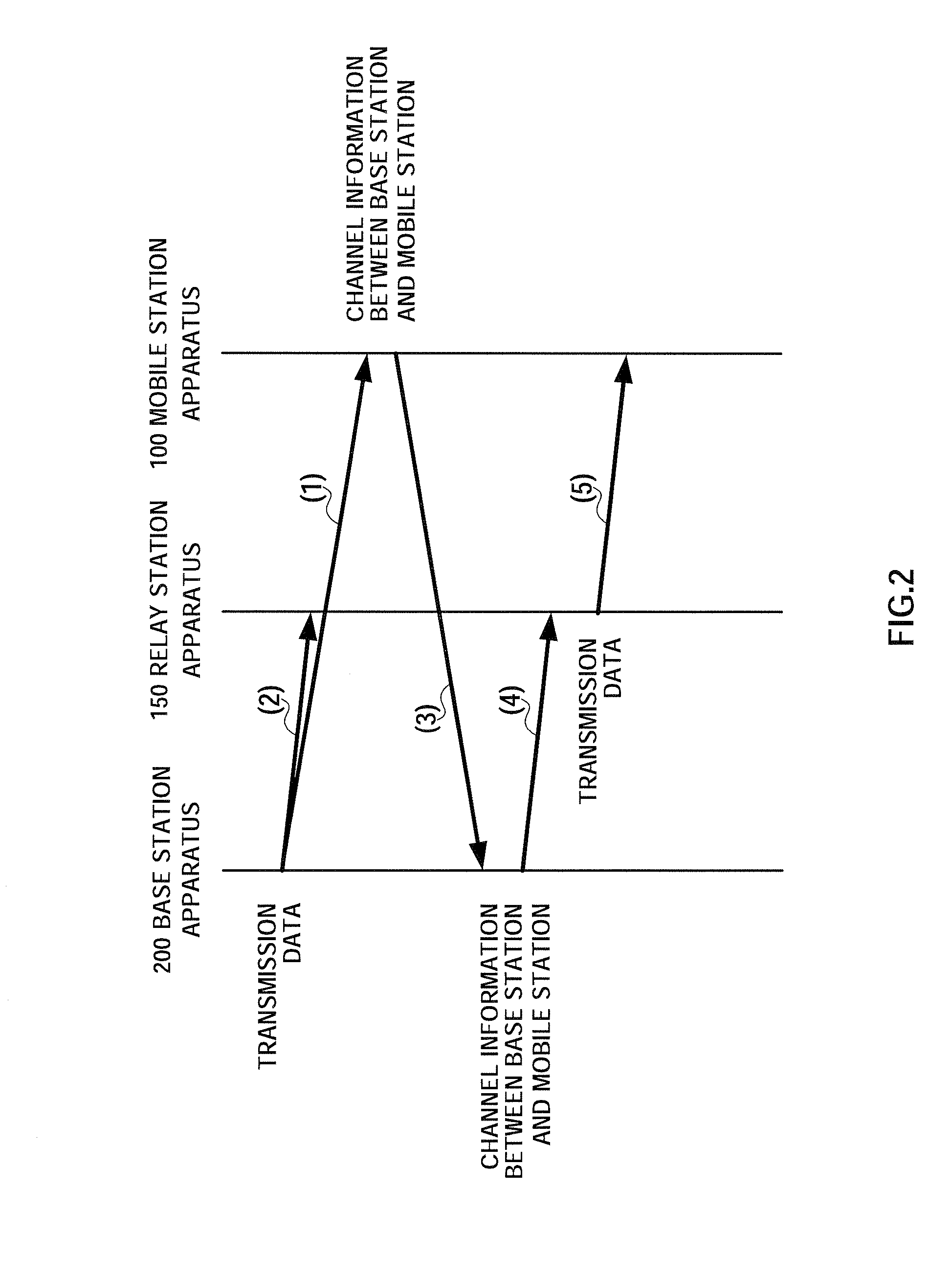
[0056] Next, the overall processing will be described using the sequence diagram shown in FIG. 2.
[0057] Base station apparatus 200 transmits a multicarrier signal to mobile station apparatus 100 and relay station apparatus 150 (processings (...
embodiment 2
[0097] In the present embodiment, an example is shown that a relay station apparatus relays a subcarrier signal having low received quality of the signal from a base station apparatus in a mobile station apparatus, by means of a subcarrier having high received quality of the signal from the relay station apparatus in the mobile station apparatus.
[0098] As shown in FIG. 10, a mobile communication system according to the present embodiment is comprised of mobile station apparatus 100, relay station apparatus 160 and base station apparatus 200.
[0099] Next, the overall processing will be described using the sequence diagram shown in FIG. 11.
[0100] Processings (1) to (4) are the same as those described in embodiment 1 (FIG. 2), and processings (1) to (4) are repeated for as many times as the number of frames. In the example shown in FIG. 11, the processings are repeated over 3 frames.
[0101] Next, mobile station apparatus 100 generates channel information in which the received quality...
embodiment 3
[0129] The present embodiment shows an example that a plurality of relay station apparatuses relay their respective managing subcarriers only.
[0130] As shown in FIG. 17, a mobile communication system according to the present embodiment is comprised of mobile station apparatus 100, a plurality of relay station apparatuses 170-1 and 170-2, and base station apparatus 200.
[0131] Next, a description will be given of the overall processing, using the sequence diagram shown in FIG. 18. The base station apparatus 200 transmits a signal to mobile station apparatus 100 (processing (1)). At this time, relay station apparatus 170-1 and relay station apparatus 170-2, as well, receive the signal transmitted from base station apparatus 200 (processings (2) and (3)). Next, mobile station apparatus 100 generates channel information which has assigning leveled received quality, and reports the channel information between this base station apparatus 200 and mobile station apparatus 100 to base stati...
PUM
 Abstract
Description
Claims
Application Information