

Image analysis by object addition and recovery
- Summary
- Abstract
- Description
- Claims
- Application Information
AI Technical Summary
Benefits of technology
Problems solved by technology
Method used
Image

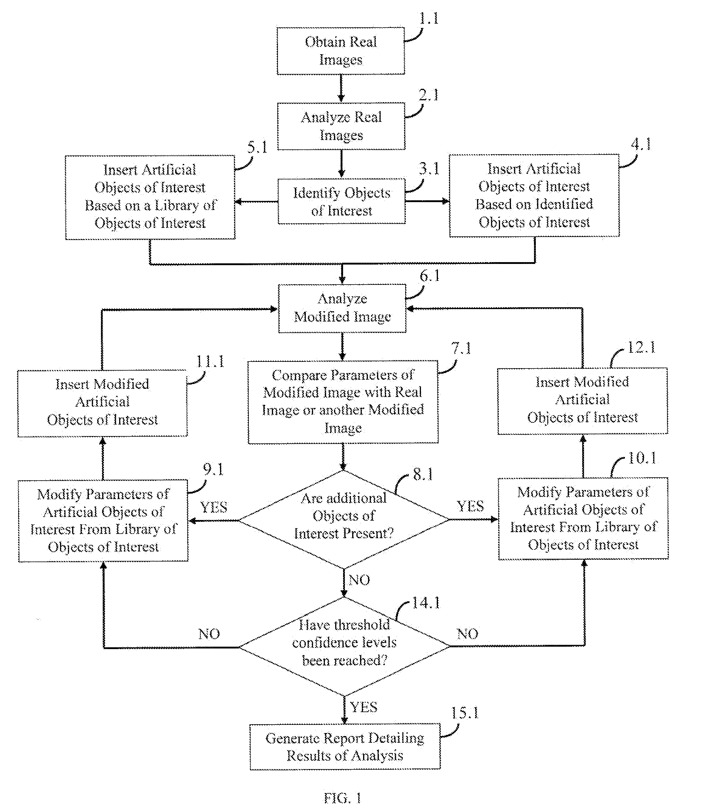
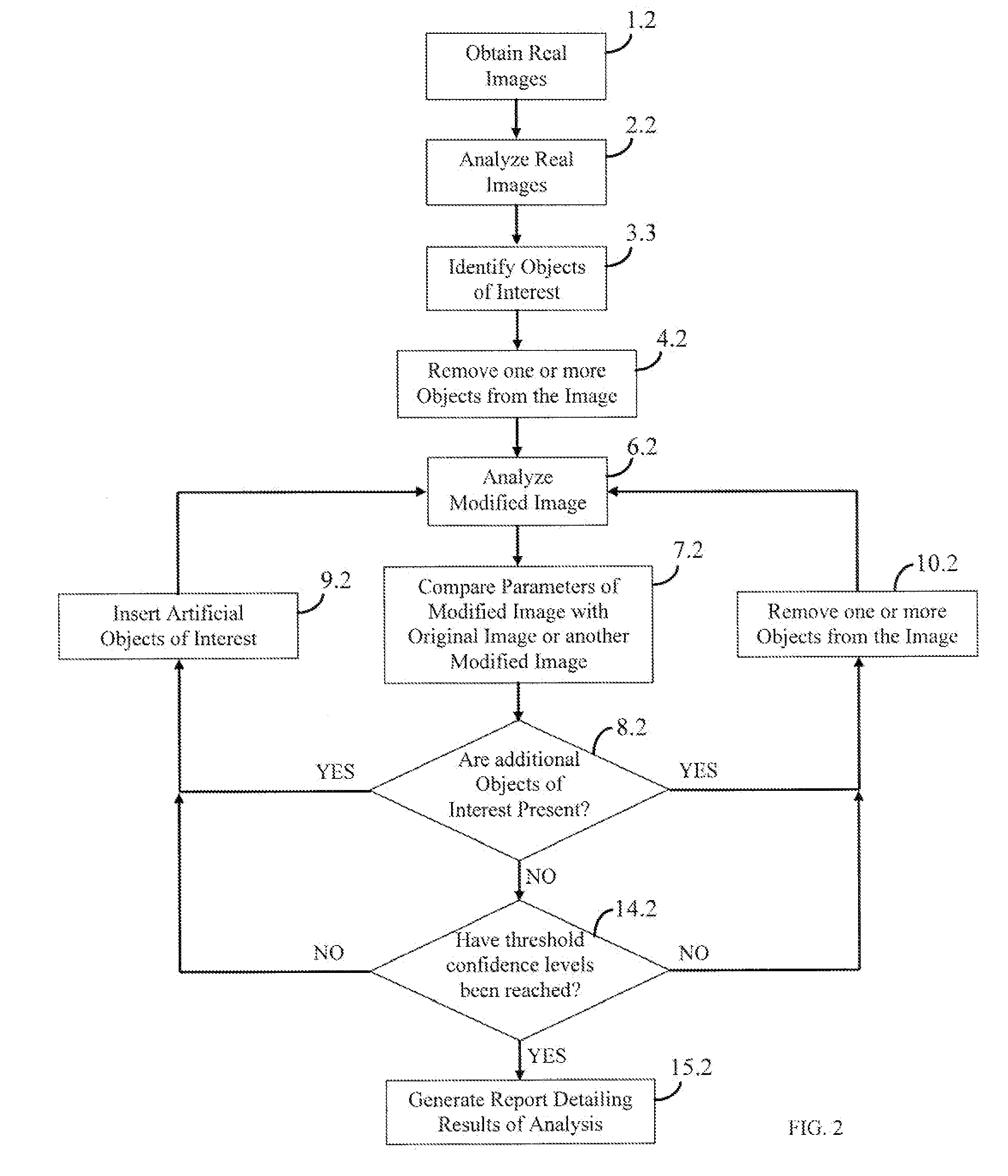
Examples
example 1
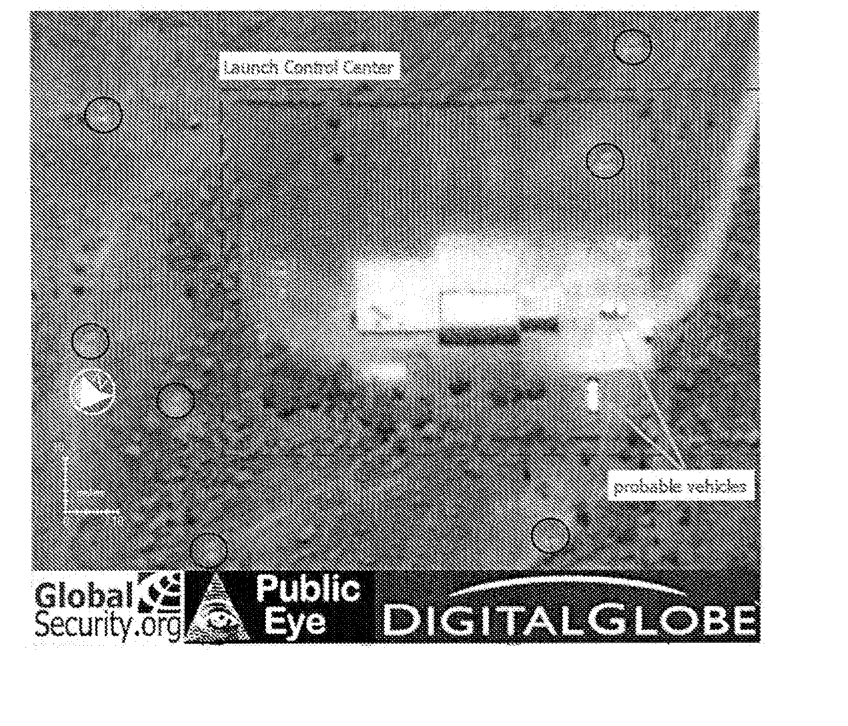
[0076]FIG. 4 is a DigitalGlobe satellite image of a facility including a large building at the center, probable vehicles to the right of the building and an object to the left of the building (circled). Initial analysis of the image concludes that the object to the left of the building is an emplacement of an anti-aircraft artillery (AAA) battery. To assess the likelihood of additional unobserved AAA emplacements being present in the image, additional objects having similar visual properties to the identified AAA emplacement have been added to FIG. 5. In FIG. 5, seven instances of the AAA emplacement noted in the previous figure have been added (circled). Subsequent reanalysis of the image of FIG. 5 may, for example, recover six instances of this particular object of interest. After repeating 100 iterations of similar analysis, it may be concluded that one would expect to observe 85% of such AAA emplacements based upon repeated reanalysis over the full terrain covered in the images ...
example 2
[0077] To demonstrate the automated approach to the problem of completeness and uncertainty estimation, Artificial Star simulation and Modeling Tool (ArtStar) toolkit on a set of 31 frames of the field of the X-ray binary GRO J1655-40 in the Galactic plane was tested using iterative image analysis. Real images are provided in FIG. 6 and FIG. 7. In these images, the field of view is mildly crowded, and the major limitation on the completeness is the resolution of the objects (stars), the brightness of the background, and the degree of cloudiness during acquisition of the images.
[0078]FIG. 6 is an example image collected of X-ray binary GRO J1655-40, located in the Galactic disk and represents “good” data. Although this image is of high quality, the level of crowding is significant due to the very high density of stars in the image. The stars in this image look bigger than those in FIG. 7 only because of the display contrast used. FIG. 7 is another example image of GRO J1655-40 and r...
PUM
 Abstract
Description
Claims
Application Information