Electric contact and socket for electrical part

a technology of electrical parts and sockets, which is applied in the direction of coupling contact members, coupling device connections, electrical apparatus, etc., can solve problems such as faults in electrical connections between electrical parts and printed circuit boards

Inactive Publication Date: 2008-03-13
ENPLAS CORP
View PDF10 Cites 10 Cited by
  • Summary
  • Abstract
  • Description
  • Claims
  • Application Information

AI Technical Summary

Benefits of technology

[0018]According to this embodiment, the pitch of the rough winding portion is smaller than that of the normal winding portion, so that after the rough winding portion is compressed so as to contact the first and second close winding portions to each other to provide a closely wound-up state, the normal winding portion can be compressed. Furthermore, by contacting the lower portion of the first close winding portion to the upper portion of the normal winding portion including portion, the electrical connection between the first and second electrical parts can be shortened (short-circuited), and the specific resistance of the electric contact can be reduced. In addition, since the first spring portion is the first close winding portion, it can be made difficult to entangle the first spring portion of one electric contact with the coil spring of another electric contact at the time of manufacturing a socket for an electrical part.
[0022]According to this embodiment, since the rough winding portion is formed between the first electrical part side contact member and the second electrical part side contact member, the electrical connection between the first and second electrical parts can be shortened at a portion at which the first and second electrical part side contact members are not contacted. In addition, the rough winding portion is contracted while inclining, so that the axis of the first spring portion can be easily inclined with respect to the axis of the second spring portion.
[0024]According to this feature, the fear of engaging the inserting projection with the inner side of the second spring portion can be prevented, and the terminal side contact member can be easily and smoothly inclined in the transverse direction.

Problems solved by technology

Therefore, in a case where the axis of the terminal of the electrical part is shifted from the axis of the terminal side contact member, the terminal side contact member does not follow the shifting of the terminal of the electrical part, which may result in fault in electric connection between the electrical part and the printed circuit board.

Method used


Image

  • Electric contact and socket for electrical part
  • Electric contact and socket for electrical part
  • Electric contact and socket for electrical part

Examples


first embodiment

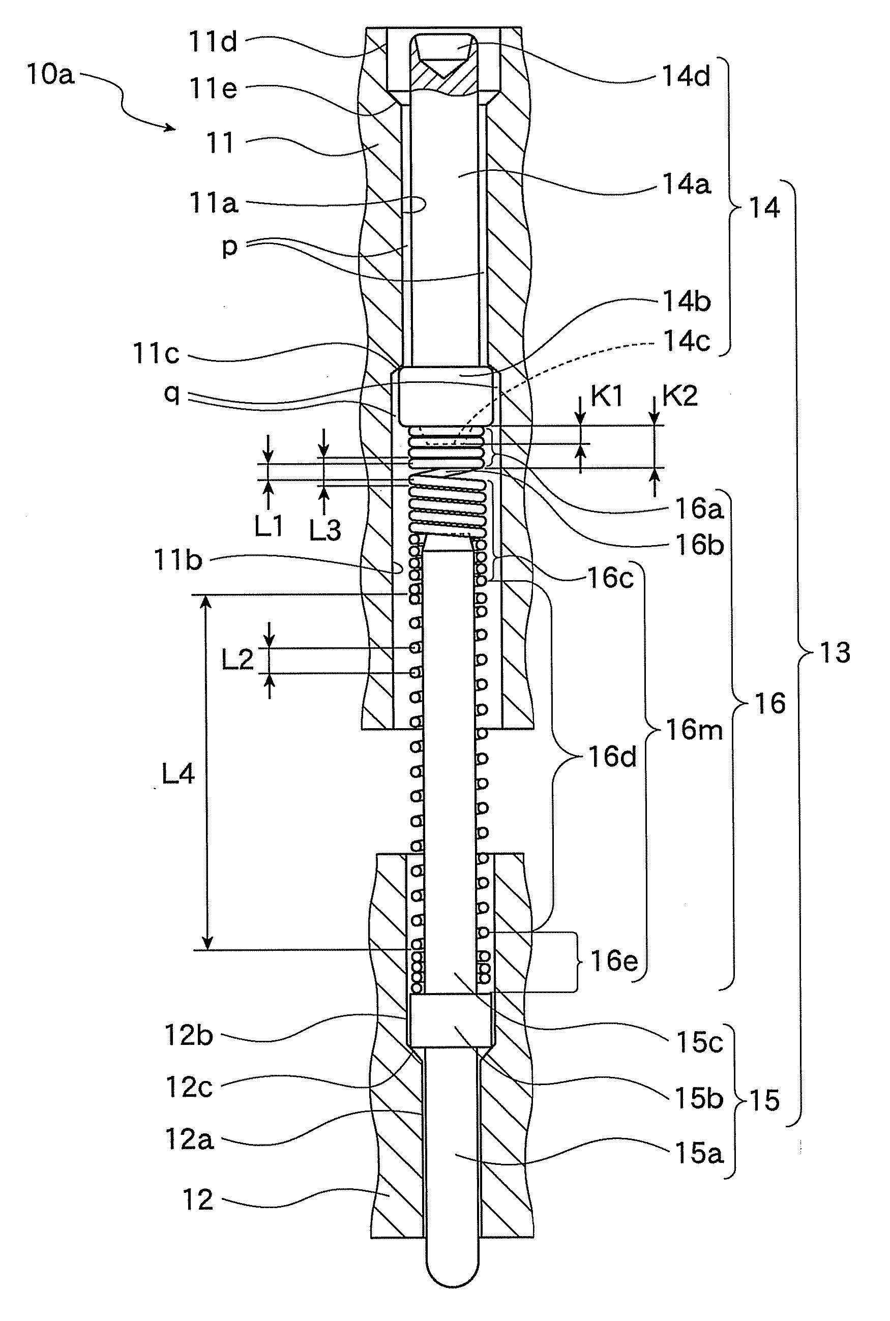
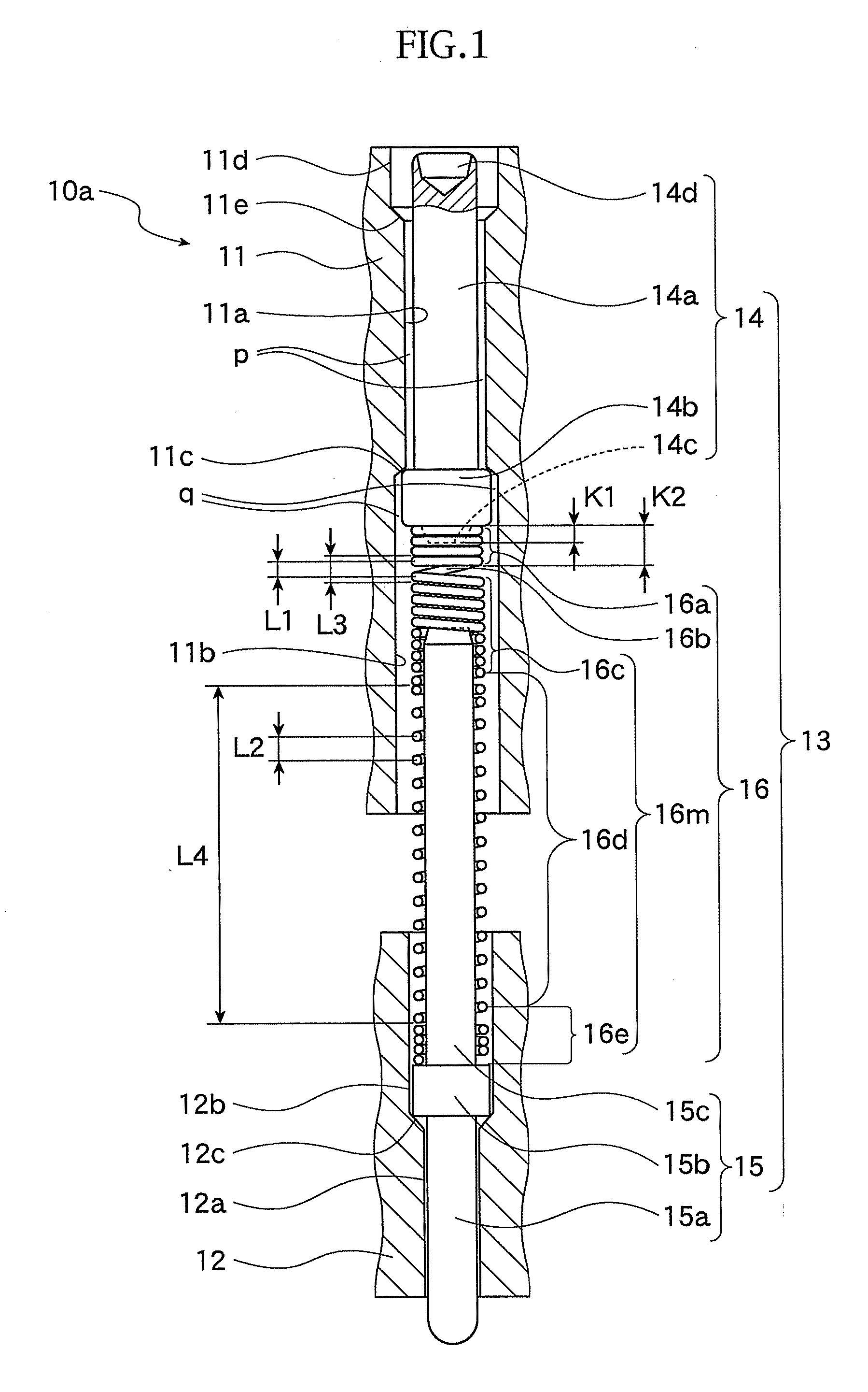
[0054]FIG. 1 to FIG. 4 represent a first embodiment of the present invention.

[0055]First, with reference to FIG. 1, a structure of the first embodiment will be briefly described.

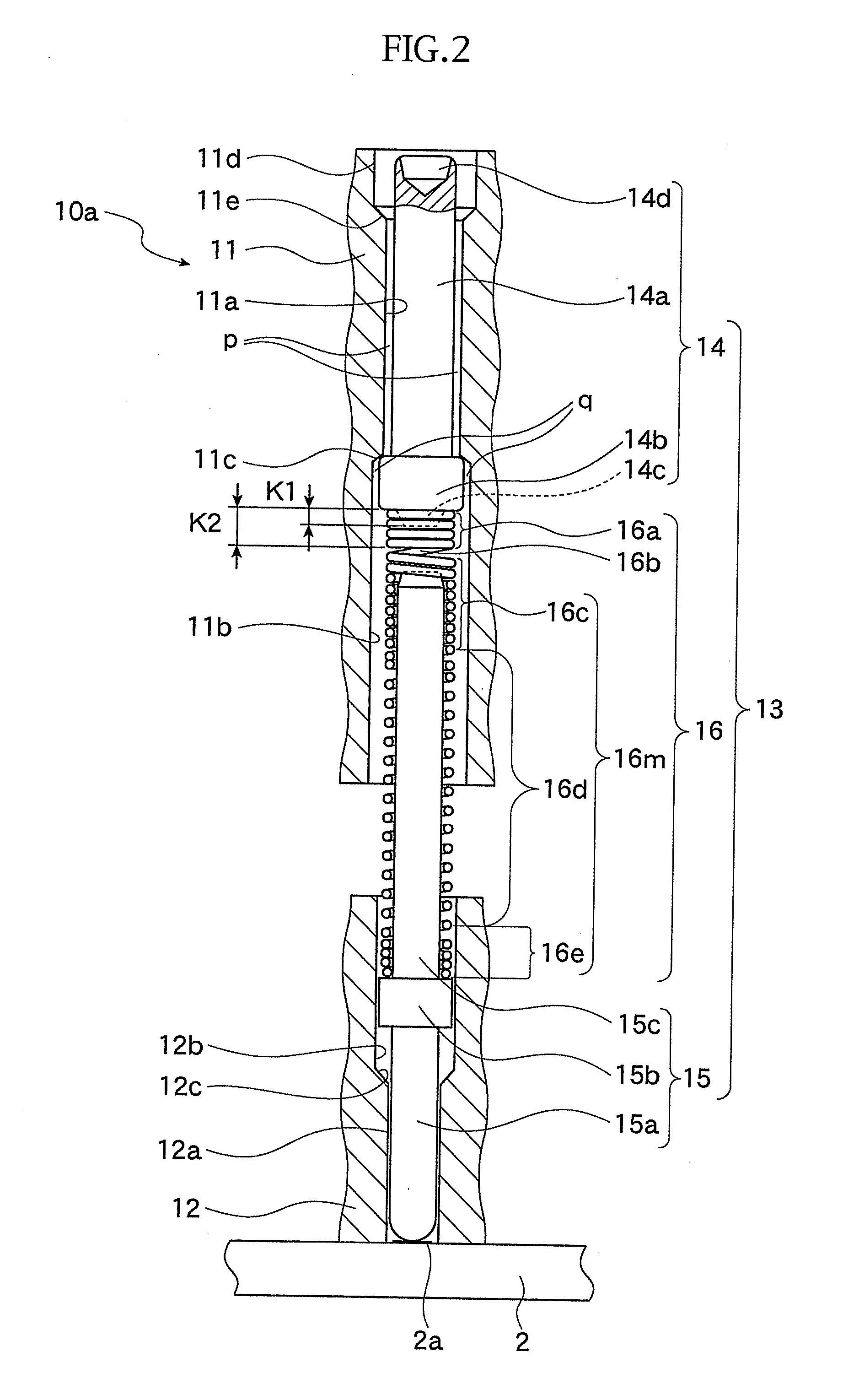
[0056]A socket body 10a of an IC socket as “socket for an electrical part” is provided with an upper plate 11 and a lower plate 12, both having a plate-shape. The socket body 10a is disposed on a printed circuit board 2 (shown in FIG. 2) and is accommodated with an IC package 1 (shown in FIG. 3) as “first electrical part”. In addition, a plurality of electric contacts 13 (or contact pins) are disposed to the socket body 10a, and the IC package 1 as first electrical part and the printed circuit board 2 as “second electrical part” are electrically connected through the electric contacts 13. Further, in FIG. 1, although only a single electric contact 13 is shown, in actual arrangement, a plurality of electric contacts 13 are arranged to the socket body 10a.

[0057]The electric contact 13 is provided with, as sho...

second embodiment

[0094]The second embodiment of the present invention will be described hereunder with reference to FIGS. 5 to 10B.

[0095]In this second embodiment, same reference numerals are added to portions or elements corresponding to those in the first embodiment, and detailed explanation thereof is omitted herein.

[0096]This second embodiment differs from the first embodiment in the point that a coil spring 26 is used in place of the coil spring 16 in the first embodiment.

[0097]In this second embodiment, as shown in FIGS. 5 to 8B, a socket body 20a of an IC socket as “socket for an electrical part” is provided with a vertically movable mount plate 21, as a “plate member”, on which an IC package 1 (FIG. 6) is mounted, an upper plate 22 and a lower plate 23.

[0098]The socket body 20a is disposed on a printed circuit board 2 (FIG. 5B, 6, 7B, or 8A), and is accommodated with the IC package 1 (FIG. 6 or 8A). A plurality of electric contacts 24 are arranged to the socket body 20a, through which the pr...

third embodiment

[0126]A third embodiment of the present invention will be described hereunder with reference to FIGS. 11A to 13, in which same reference numerals are added to portions or elements corresponding to those of the second embodiment.

[0127]The third embodiment of the present invention differs from the second embodiment in that the substrate side contact member 15 disposed in the second embodiment is not disposed in the third embodiment. In addition, in the second embodiment, the terminal side contact member 14 is provided with the inserting projection 14c which is inserted into the coil spring, but in this third embodiment, a terminal side contact member 35 is provided with an inserting shank portion 35c which is inserted into the coil spring, in place of the inserting projection 14c.

[0128]In addition, in the second embodiment, the coil spring 26 includes the small pitch winding portion 26a as “first spring portion” on the IC package side, and the large pitch winding portion including po...


PUM


Abstract

An electric contact of a socket for an electrical part is disposed between a first electrical part and a second electrical part so as to electrically connect the first and second electrical parts, and includes: a first electrical part side contact member contacting the first electrical part; a second electrical part side contact member contacting the second electrical part, the coil spring including a first spring portion abutting against the first electrical part side contact member and a second spring portion abutting against the second electrical part side contact member. When the first electrical part contacts the first electrical part side contact member, an axis of the first spring portion inclines with respect to an axis of the second spring portion, and then, a portion of the first electrical part side contact member on a side contacting the first electrical part is transversely moved.

Description

BACKGROUND OF THE INVENTION[0001]1. Field of the Invention[0002]The present invention relates to an electric contact disposed between a first electrical part and a second electrical part for electrically connecting them, and also relates to a socket for an electrical part provided with such electric contact.[0003]2. Related Art[0004]A prior art provides a socket for an electrical part provided with an electric contact disposed between a first electrical part and a second electrical part so as to electrically connect them. For example, there has been provided a socket for an electrical part, which is provided with a socket body disposed on a printed circuit board and accommodated with an electrical part, in which the printed circuit board and the electrical parts are electrically connected through a plurality of electric contacts or contact pins disposed to the socket body. In a structure in which the electric contact has a terminal side contact member contacting a terminal of the el...

Claims


Application Information

Patent Timeline
Patent Type & Authority Applications(United States)
IPC IPC(8): H01R13/33
CPCH01R13/2421H01R33/76
Inventor OHSHIMA, HISAOAZUMI, LEO
Owner ENPLAS CORP
Why Eureka
Try Eureka