Device for hygienizing, warming, and dehumidifying a beehive

US20080064298A1Inactive Publication Date: 2008-03-13JUNQUEIRA DE SOUZA MARCIO +2

Image

  • Device for hygienizing, warming, and dehumidifying a beehive
  • Device for hygienizing, warming, and dehumidifying a beehive
  • Device for hygienizing, warming, and dehumidifying a beehive

Examples


Embodiment Construction

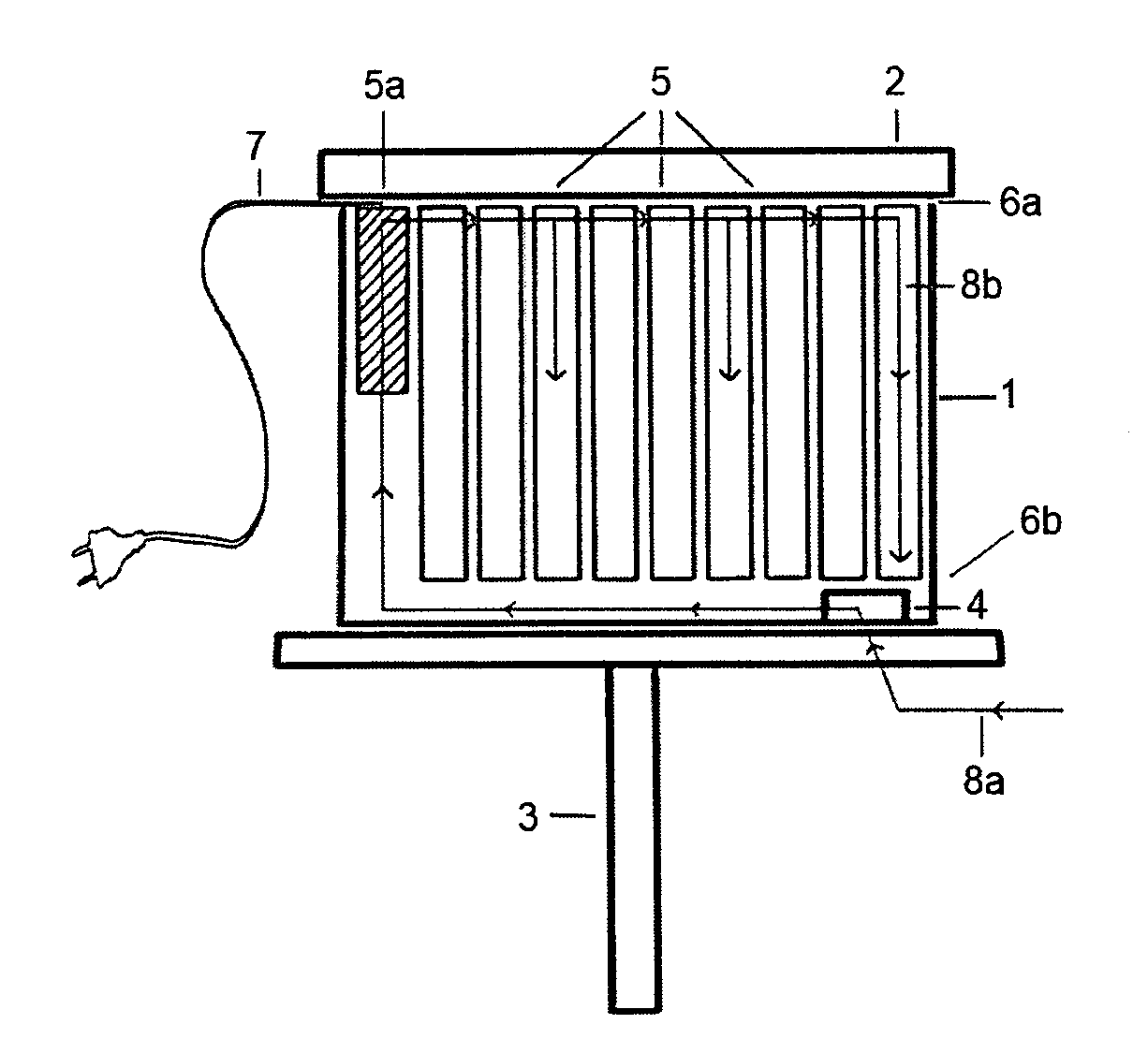
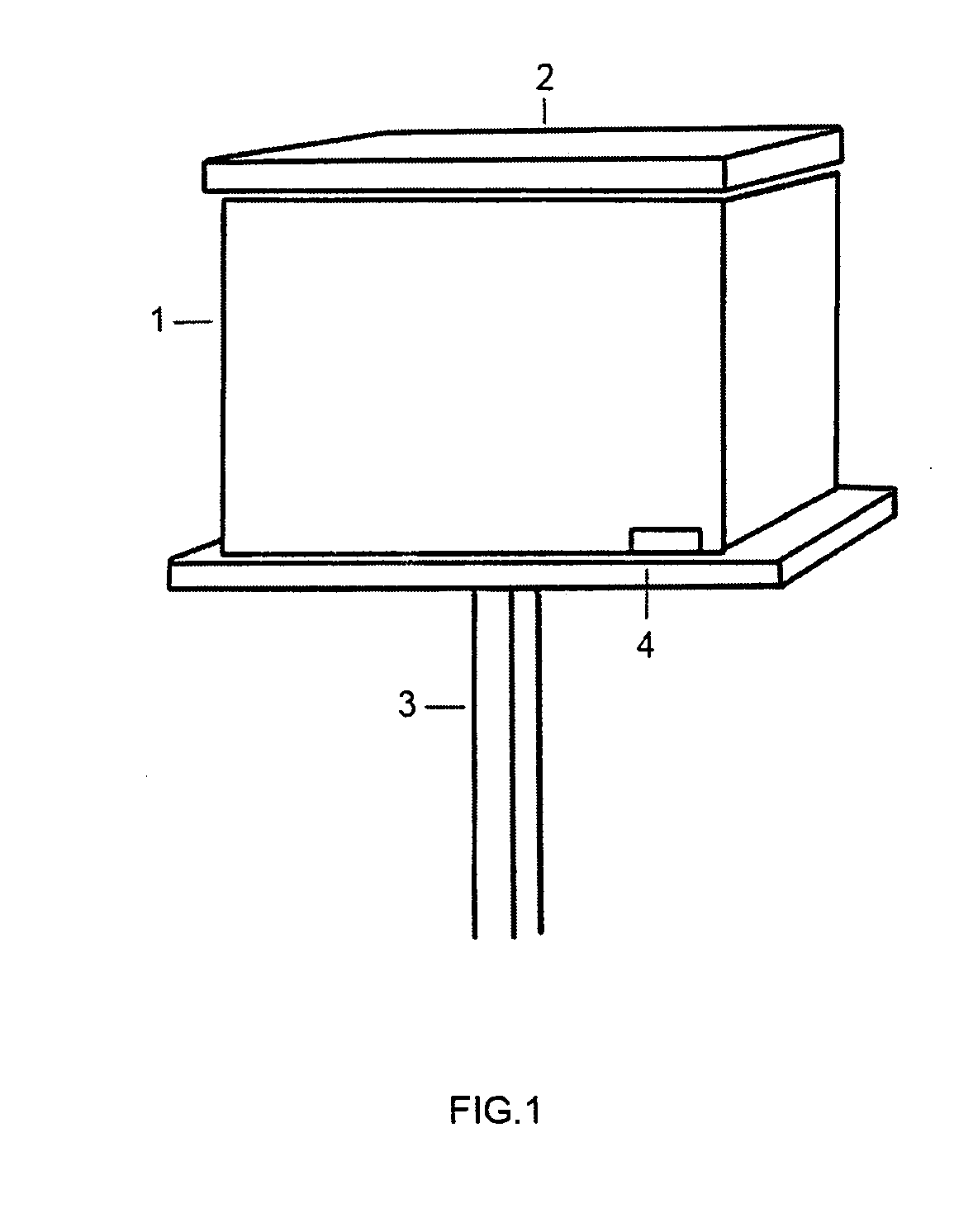
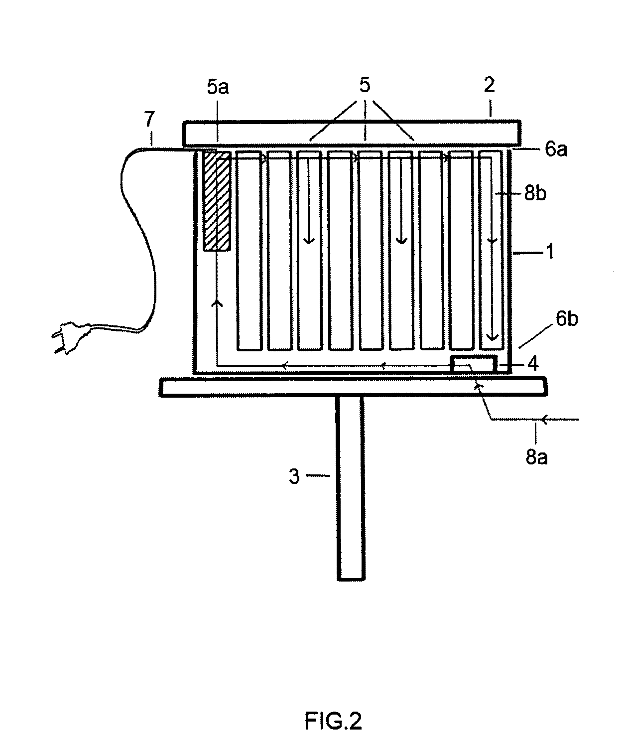
[0062]One aspect of the invention is a device for the optimization of organic bee produce.

[0063]Another aspect of the invention is a process for optimization of organic bee produce with the aid of the inventive device.

[0064]Still another aspect is that the device and process of the invention, since they keep the bees of a bee box in a healthy state throughout the whole year, lead to increased yields in the pollination of agricultural cultures relative to state-of-the-art bee boxes, that is, those from which the present device is absent.

[0065]The inventive device is applicable to all the usual kinds of bee boxes, or nest boxes such as Langstroth, Schirmer e Curtinaz, as such or adapted in any way.

[0066]Organic bee produce of improved yield obtained from the insertion of the inventive device in a bee box include honey, propolis (conventional and green), royal jelly, wax, pollen, bee venom and any similar related bee produce.

[0067]The present invention has been developed based on the p...


PUM


Abstract

A device 30 and associated process are described for hygienizing and warming beehives aiming at the improvement of the production of organic bee produce, said device comprising providing a bee box 1 containing frames 5 for honey production and bee housing, one frame 5a being left for inserting a ceramic block 11 provided with at least one row containing from 8 to 32 channels 11a and where the lower and upper ends of these channels 11a are opened towards the interior of the beehive, channels 11a being thermally insulated from the remaining of frame 5a with the aid of wings 15a, 15b and traversed by conducting filaments 14a, 14b connected to an energy source 20 through wire 7, whereby whenever electrical current traverses said filaments 14a, 14b the temperature inside said channels attains from 300-350° C. with the consequent heating of circulating air in the beehive by convection, the warmed air from the upper ends of said channels creating a negative pressure in the lower ends of same, whereby the outer colder air is sucked towards the interior of said channels, alternatively by using a fan or air pump, with the consequent extermination of the microorganisms present in the air as they cross warmed channels 11a.

Description

FIELD OF THE INVENTION[0001]The present invention relates to the field of the devices for hygienizing, warming and dehumidifying beehives, more specifically, to an electromechanical device for fighting several pathogenic agents that harm those insects such as viruses, fungi, bacteria, mites, mold, spores and mildew, through hygienizing, dehumidifying, and warming the air that circulates in a bee box using mainly air convection so as to provide heat to the bee colony.BACKGROUND INFORMATION[0002]The concept of employing the thermal effect as a sterilizing agent is generally well-known, as well as is the concept that the Joule effect can be used as a source of heat. Examples of state-of-the-art devices using such effect for cleaning or purifying the air by means of a tubular or elongated passage associated to a heating device can be found in U.S. Pat. Nos. 2,014,455, 2,564,898 and 3,691,346. Such devices require relatively high power input, give out a flow of concentrated air and / or re...

Claims


Application Information

Patent Timeline
13 Mar 2008
Publication
US20080064298A1
IPC
A01K51/00; A01K47/06
CPC
A01K51/00; A01K47/06
Inventors
JUNQUEIRA DE SOUZA, MARCIO; REGATTIERI SAMPAIO, MARCELO