Incorporating Internal Anatomy In Clinical Radiotherapy Setups

a technology of internal anatomy and clinical radiotherapy, which is applied in the field of improving clinical setups in radiotherapy, can solve the problems of poor indication of the actual location of the underlying tumor bed, and achieve the effect of accurate patient setups and facilitate the combination of images

Active Publication Date: 2008-03-13
ELEKTA AB
View PDF101 Cites 69 Cited by
  • Summary
  • Abstract
  • Description
  • Claims
  • Application Information

AI Technical Summary

Benefits of technology

[0007] The present invention facilitates the combination of images of internal anatomical information (such as seroma) obtained using ultrasound with visual external cues in order to achieve accurate patient setups for the delivery of radiotherapy treatments. The following embodiments are primarily described in relation to electron breast boosts augmented with 3D ultrasound images, but the methods and devices described herein may be applied to any radiation-therapy clinical setup procedure, such as many types of electron boost treatments, or any clinical setup using other photon or proton radiation beams, for example.
[0010] In conjunction with the display of the image, the motion of the patient support device (e.g., a treatment couch), and the gantry and collimator angles of the linac, can be tracked automatically by a tracking system or, in some cases, can be entered directly via an input device (in some cases the display screen itself) by a technician. Features of the image can be manually or automatically contoured on the display while being presented to the technician from the point of view of the treatment beam (“beam's-eye view”). This image may be updated as the technician moves the gantry or the patient support. In this way, the technician can complete the clinical setup procedure using the visual cues of the patient / linac combination (e.g., a surgical scar, the areola, an en face beam, a fixed SSD) with the augmented information of the internal features of interest as seen on-screen (in real time or refreshed as needed).
[0011] Once the gantry and patient support device are correctly aligned to target the internal and external features, the invention facilitates the design of a treatment aperture, such as an electron cutout, to encompass both types of features. The technique can include drawing a desired treatment area or specific landmarks on the skin, drawing treatment areas or specific landmarks on the visual display, and / or transferring information between these two representations. In some embodiments, the transfer of features from skin to visual display is accomplished using a pointer tool tracked by an optical camera, or a camera system which directly images the drawn contours and transmits them to the visual display via a computer or network. In other embodiments, the transfer from visual display to skin is accomplished by printing information from the visual display to scale on a transparency, affixing the transparency to the electron cone, and tracing the cutout on the patient's skin. The resulting aperture can be built by, for example, creating cerrobend blocks for electron treatments.

Problems solved by technology

Unfortunately, the location of the scar, which is used often as a proxy for the lumpectomy site to aim the electron beam, is often a poor indicator of the actual location of the underlying tumor bed.

Method used


Image

  • Incorporating Internal Anatomy In Clinical Radiotherapy Setups
  • Incorporating Internal Anatomy In Clinical Radiotherapy Setups
  • Incorporating Internal Anatomy In Clinical Radiotherapy Setups

Examples


Embodiment Construction

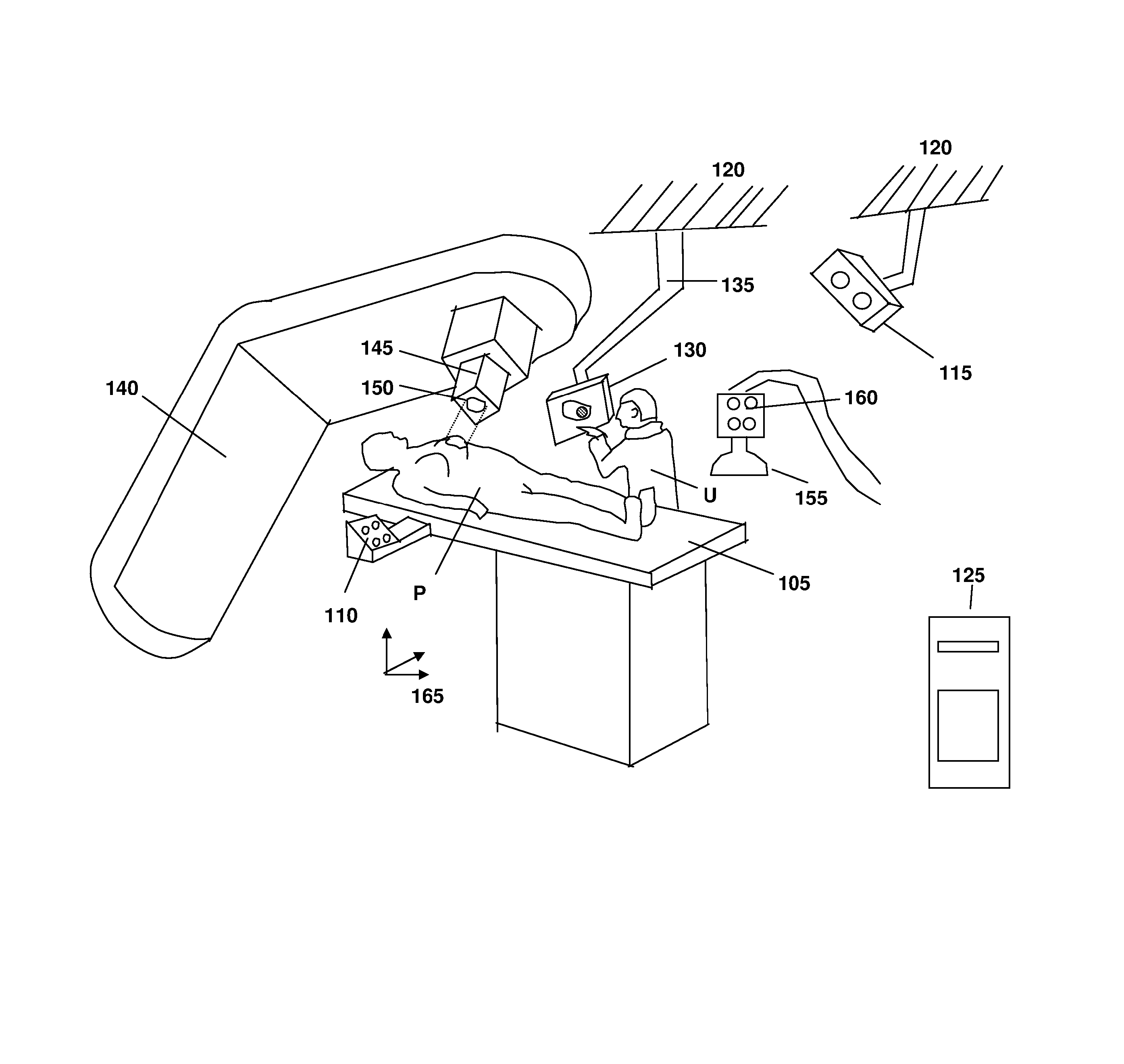
[0021]FIG. 1 illustrates one embodiment of the invention in which a patient P is situated on a patient support device such as a treatment couch 105. The couch 105 is tracked using a set of reflecting or emitting markers 110, which are detected and monitored by an optical camera 115 attached to the ceiling 120 of the treatment room. Alternatively, the camera may be attached to other fixed and known positions in the room such as walls, beams and / or fixtures. The output of the camera 115 is transmitted (using wired or wireless channels) to a computer 125 having an associated visual display 130. In some instances, the computer 125 is located outside the treatment room to avoid radiation damage. The visual display 130 can be cart-based but is preferably mounted to a swing arm 135 attached to the ceiling 120, such that the user U (e.g., a radiation therapist, a dosimetrist, a medical physicist or a radiation oncologist) can move the visual display 130 to any convenient location. A linear ...


PUM


Abstract

A diagnostic image of internal anatomical features of a patient is annotated with representations of external features, such both can be viewed together on a visual display. Adjustments to various treatment parameters relating to the administration of radiation therapy are provided, and the displayed image is automatically updated based on the adjustments.

Description

CROSS-REFERENCE TO RELATED APPLICATIONS [0001] This application claims priority to and the benefit of, and incorporates herein by reference, in its entirety, provisional U.S. patent application Ser. No. 60 / 844,163, filed Sep. 13, 2006.TECHNICAL FIELD [0002] This invention relates to methods and systems for improving clinical setups in radiotherapy. BACKGROUND INFORMATION [0003] External beam radiotherapy for breast cancer is typically delivered by opposing tangential fields which provide a uniform dose to the entire affected breast. The treatment is given over a number of sessions, and is often followed by additional boost sessions. The boost sessions are typically delivered with an electron beam, which is designed to treat the primary lumpectomy site only. [0004] Unlike photons, whose intensity decreases in an approximately exponential fashion within the patient, electrons deposit most of their dose within a fixed, finite range which depends on the energy of the beam. Thus, a singl...

Claims


Application Information

Patent Timeline
Patent Type & Authority Applications(United States)
IPC IPC(8): A61B5/05
CPCA61B5/055A61B6/03A61N2005/1058A61B8/483A61N5/1049A61B8/08
Inventor FALCO, TONYLACHAINE, MARTINGORMAN, JASON
Owner ELEKTA AB
Why Eureka
Try Eureka