
Method for sequential programming of an injection molding cycle of an injection molding machine

Inactive Publication Date: 2008-03-13
KRAUSSMAFFEI TECH GMBH
View PDF11 Cites 7 Cited by
  • Summary
  • Abstract
  • Description
  • Claims
  • Application Information

AI Technical Summary

Benefits of technology

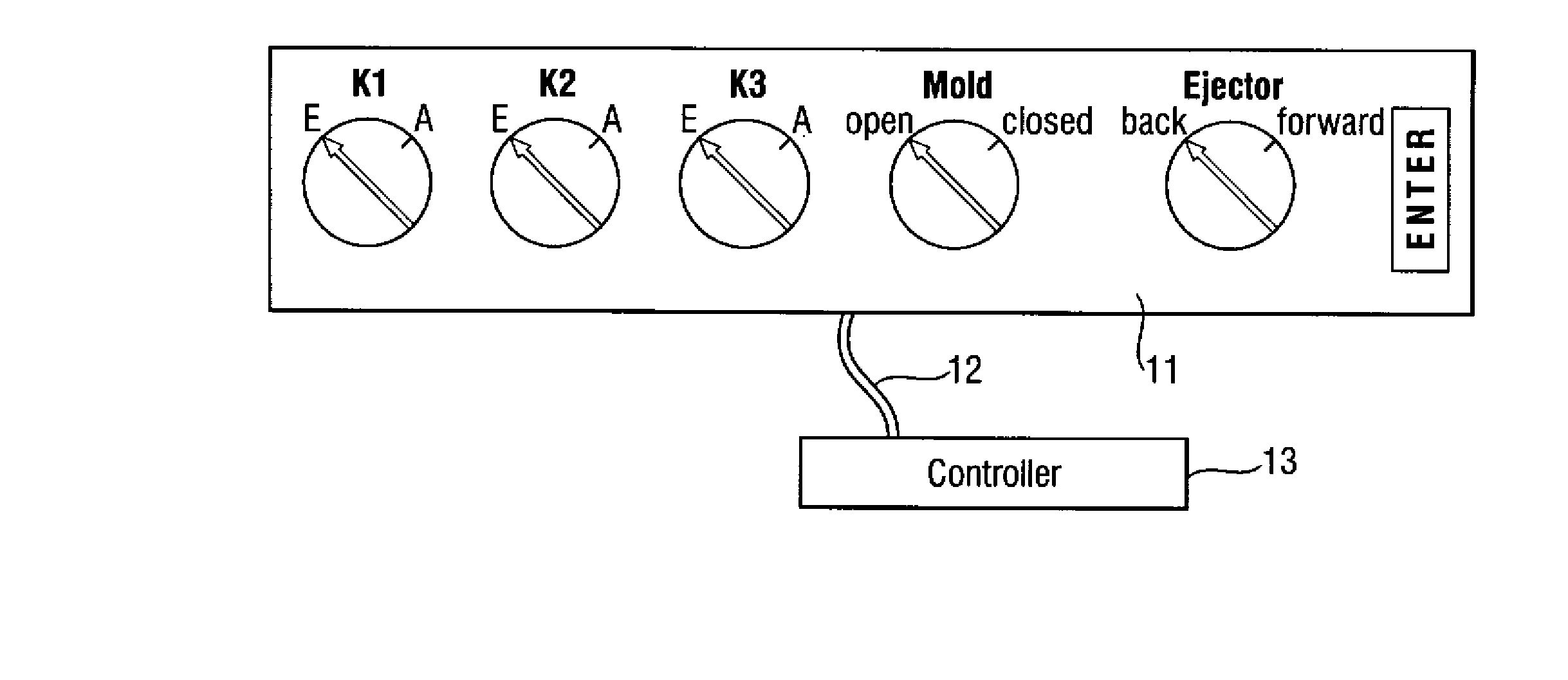
[0015] By having an operator manually execute the injection molding cycle step-by-step and displaying to the operator during programming where the machine parts and / or mold sections, such as cores, are moved, is becomes unimportant how of the respective accessed position or the accessed state is identified. This prevents errors of the kind that can occur with manually programmed stored program controllers, when expressions such as “moved in” and “moved out” are misinterpreted and when the entire movement is executed in one pass at the end of the completed programming process. In addition, an operator can implement even complex process flows without having detailed knowledge about the controller; only the movement of the molds must be known. The method has the additional advantage that errors can be identified before they become critical.
[0016] The resulting forces during movement of the machine parts and / or mold parts are drastically reduced when the teach-in takes place in the setup mode, thus minimizing damage in the event of errors.
[0017] According to another feature of the present invention, after the teach-in is completed, the process flow can be optimized by having the operator execute the injection molding cycle one-time automatically, and by subsequently changing the parameters to optimize the process. For example, the ejector or a core puller can be moved faster by suitably increasing the quantity of hydraulic fluid, for example in hydraulic injection molding machines.

Problems solved by technology

When programmed online, the injection molding machine is unavailable for production during a considerable length of time.
Disadvantageously, the process flow of an injection molding cycle in these controllers cannot be changed or only with the assistance from the machine manufacturer.
It already proves difficult to be competent with a stored program process control from a single manufacturer; and if a person is not constantly involved with this particular program and / or if a new process needs to be programmed after some time (for example, because a different product needs to be manufactured), then the person must become again familiar with this program, which may be quite time-consuming.
The situation becomes more complicated, when injection molding machines from different manufacturers must be programmed which requires familiarity with different stored program process controllers.
Moreover, these flow diagrams are not available for each mold.
In addition, errors may occur when a data describing positions, such as “advanced” and “returned”, or “moved in” and “moved out” are not unambiguous.
Moreover, operating personnel frequently does not have the required technical knowledge of the injection molding machines and molds.
All stored program controllers (SPS) and the afore-described stored program process controllers have an inherent problem in that the entire injection molding cycle is first entered in the controller and thereafter executed in its entirety, without being able to risk-free test the cycle or sections of the cycle.
Any errors can severely damage the molds.

Method used


Image

  • Method for sequential programming of an injection molding cycle of an injection molding machine
  • Method for sequential programming of an injection molding cycle of an injection molding machine
  • Method for sequential programming of an injection molding cycle of an injection molding machine

Examples


Embodiment Construction

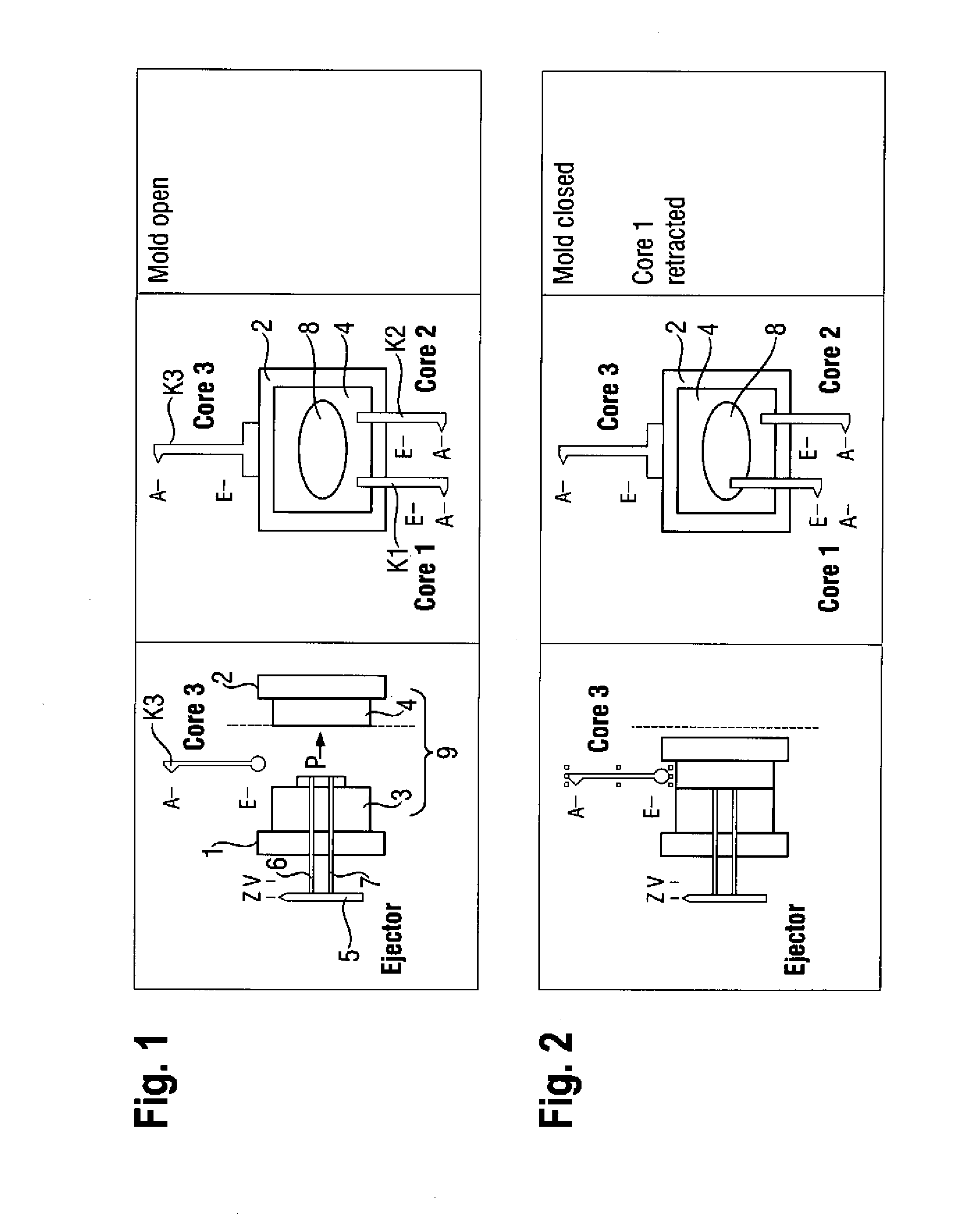
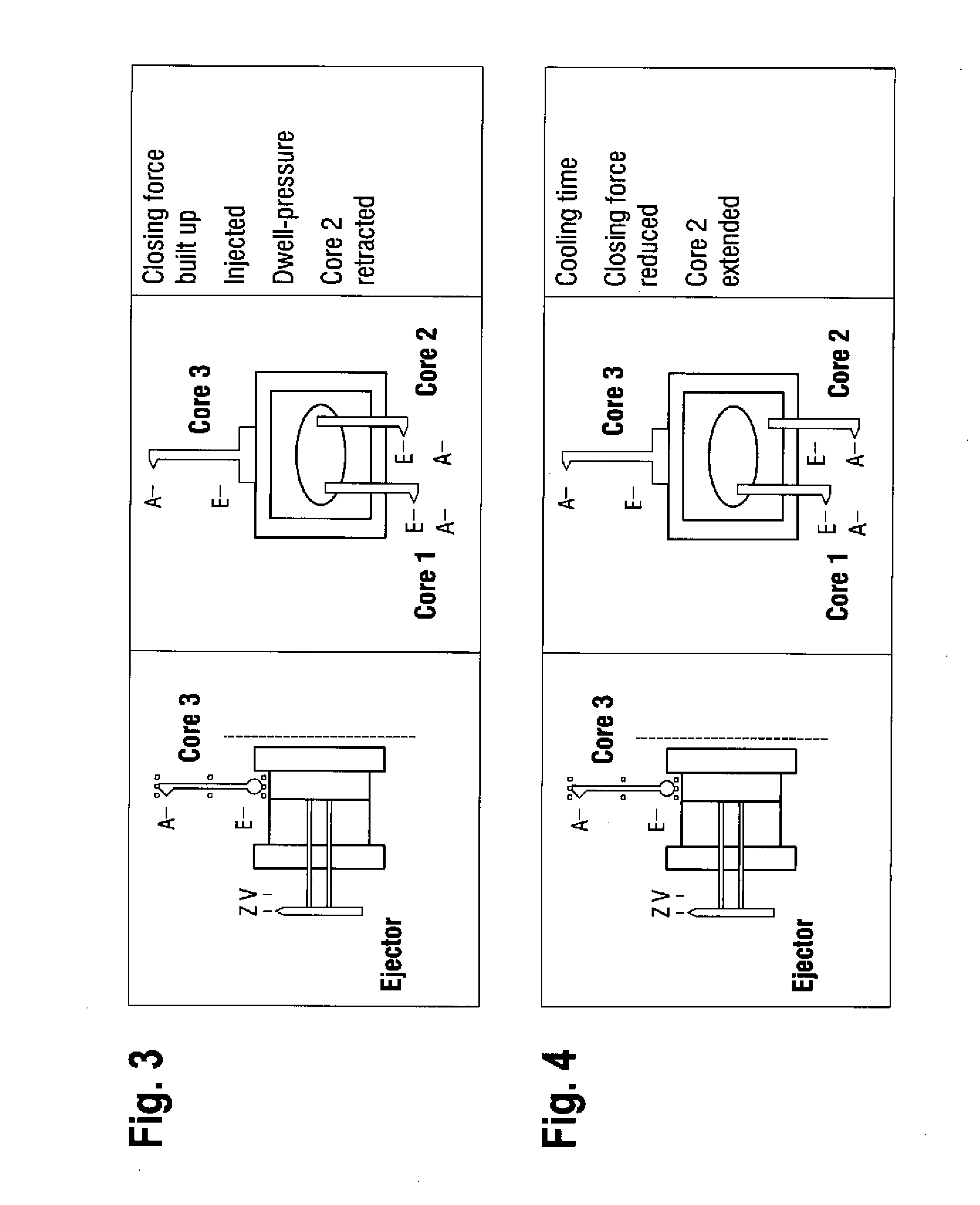
[0024] Throughout all the figures, same or corresponding elements may generally be indicated by same reference numerals. These depicted embodiments are to be understood as illustrative of the invention and not as limiting in any way. It should also be understood that the figures are not necessarily to scale and that the embodiments are sometimes illustrated by graphic symbols, phantom lines, diagrammatic representations and fragmentary views. In certain instances, details which are not necessary for an understanding of the present invention or which render other details difficult to perceive may have been omitted.

[0025] The Figures shows schematically a movable and a fixed mold platen 1 and 2 with mold halves 3 (movable) and 4 (fixed) of an injection mold 9 of a conventional injection molding machine which is not illustrated in detail. An ejector plate 5 with two ejector rods 6 and 7 is arranged on the movable mold platen 1, wherein the ejector plate 5 can be moved back and forth b...


PUM


Abstract

In a method for sequentially programming an injection molding cycle of an injection molding machine comprising one or several injection molds, the injection molding cycle is started manually step by step. The parts of the injection molding machine and / or the parts of the injection mold(s) are manually displaced into the positions or states required for the injection molding cycle in the order required for the injection molding cycle. The movement sequence (the actions and the obtained states) of the machine parts and / or the mold parts is stored in a controller.

Description

CROSS-REFERENCES TO RELATED APPLICATIONS [0001] This application is a continuation of prior filed copending PCT International application no. PCT / EP2006 / 061800, filed Apr. 25, 2006, which designated the United States and has been published but not in English as International Publication No. WO 2006 / 125706 and on which priority is claimed under 35 U.S.C. §120, and which claims the priority of German Patent Application, Serial No. 102005023919.6, filed May 24, 2005, pursuant to 35 U.S.C. 119(a)-(d), the content(s) of which is / are incorporated herein by reference in its entirety as if fully set forth herein.BACKGROUND OF THE INVENTION [0002] The present invention relates to a method for sequential programming of an injection molding cycle of an injection molding machine. [0003] Nothing in the following discussion of the state of the art is to be construed as an admission of prior art. [0004] An injection molding cycle, i.e., the operation of an injection molding machine, can be program...

Claims


Application Information

Patent Timeline
IPC IPC(8): B29C45/76B29C45/00
CPCB29C45/33B29C45/762B29C2945/7617B29C2945/76244G05B2219/45244B29C2945/76317G05B19/40937G05B19/42G05B2219/36425B29C2945/76284B29C2945/76254Y02P90/02
Inventor GRIMM, GUNTHERBETSCHE, MARKUSHUNOLD, DIETRICH
Owner KRAUSSMAFFEI TECH GMBH
Learn More