Internal mode switch bit pattern for clutch-to-clutch transmissions

a technology of clutch-to-clutch transmission and internal mode switch, which is applied in the direction of mechanical equipment, instruments, transportation and packaging, etc., can solve the problems of ims failure and inaccurate pattern sending to the control system

Inactive Publication Date: 2008-03-13
GM GLOBAL TECH OPERATIONS LLC
View PDF8 Cites 4 Cited by
  • Summary
  • Abstract
  • Description
  • Claims
  • Application Information

AI Technical Summary

Problems solved by technology

It can be foreseen that a failure may occur in the IMS such that an inaccurate pattern is sent to the control system.

Method used


Image

  • Internal mode switch bit pattern for clutch-to-clutch transmissions
  • Internal mode switch bit pattern for clutch-to-clutch transmissions
  • Internal mode switch bit pattern for clutch-to-clutch transmissions

Examples


Embodiment Construction

[0015]The following description of the preferred embodiment(s) is merely exemplary in nature and is in no way intended to limit the invention, its application, or uses. For purposes of clarity, the same reference numbers will be used in the drawings to identify similar elements. As used herein, the term module refers to an application specific integrated circuit (ASIC), an electronic circuit, a processor (shared, dedicated, or group) and memory that executes one or more software or firmware programs, a combinational logic circuit, and / or other suitable components that provide the described functionality.

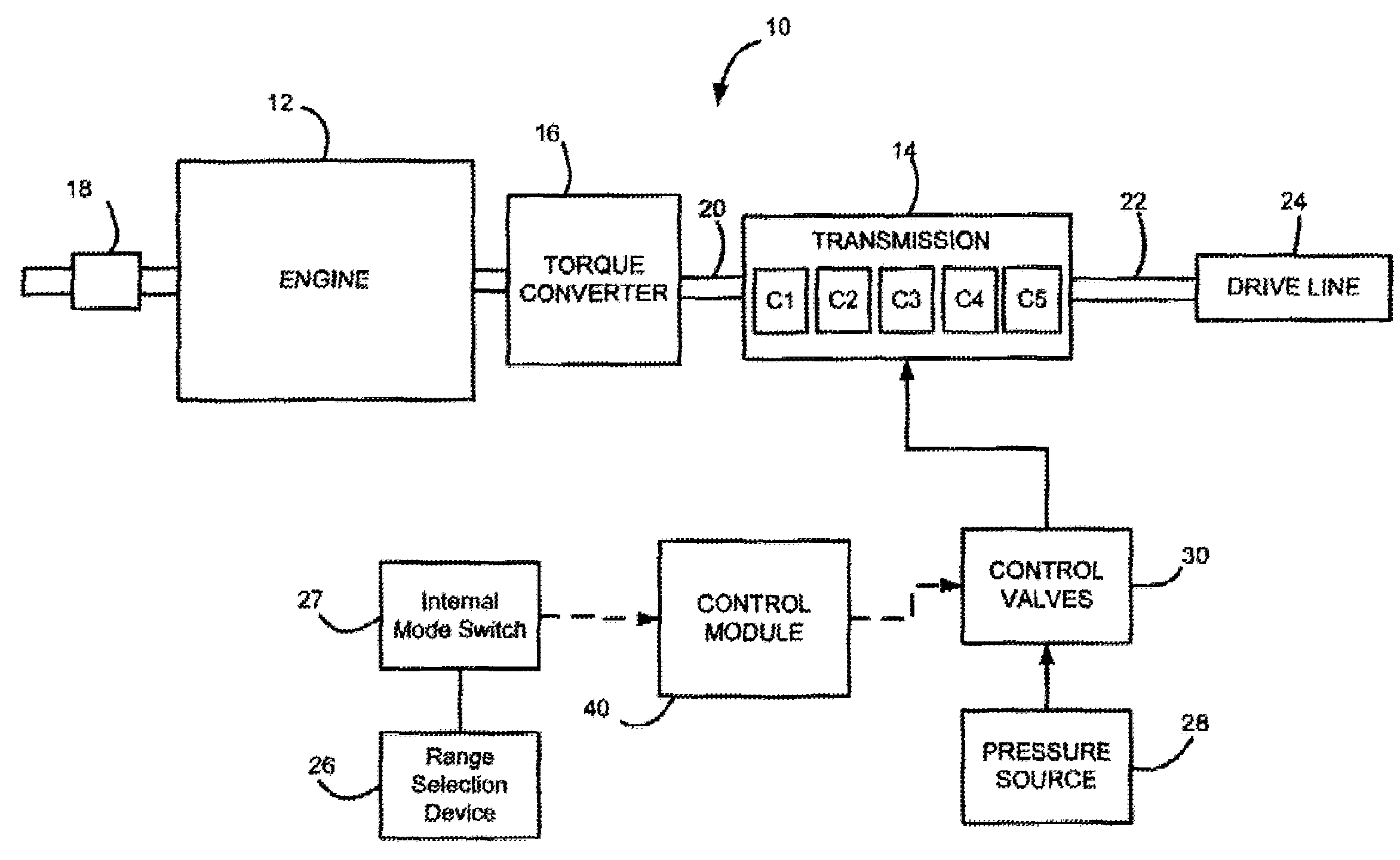
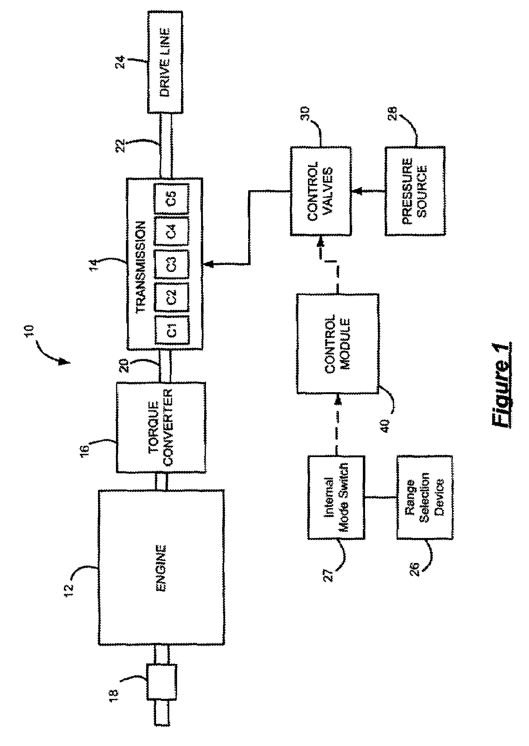
[0016]Referring now to FIG. 1, a vehicle is shown generally at 10. The vehicle includes an engine 12 that drives a transmission 14 through a torque converter 16. Air is drawn into the engine 12 through a throttle 18. The air is mixed with fuel and combusted within cylinders (not shown) of the engine 12 to produce drive torque. The torque converter 16 supplies the engine torque to the...


PUM


Abstract

A method for determining a position of a range indication device for an automatic transmission is provided. The method includes: receiving N bits corresponding to a state of N circuits, respectively, wherein the N bits are related to a position of a range indication device and wherein the position includes transmission range states and transitional states between the transmission range states; associating the bit patterns with at least one of the transitional states and the transmission range states; defining the bit pattern having N bits equal to a first state as the transitional state, and defining the bit pattern having N / 2 bits equal to one of the first state and a second state as the transmission range state.

Description

FIELD OF THE INVENTION[0001]The present invention relates to methods and systems for indicating a state of a range indication device for automatic transmissions.BACKGROUND OF THE INVENTION[0002]An internal mode switch (IMS) is a component of a transmission used to relay the driver's selected range intent to a control system of a vehicle. The IMS is a sliding contact electrical switch assembly attached to a lower control valve body of the transmission. Conventional switches consist of two major components: a housing, which houses at least six tracks of conductive and non-conductive material that make up stationary contacts, and an insulator assembly, which makes up the moving contacts and is linked to an operator controlled shift lever. The six tracks include circuit A, circuit B, circuit C, circuit P, a park-neutral circuit, and a ground circuit.[0003]The IMS is electrically connected to a control system of the vehicle via at least five wires (voltage is supplied to four and one is ...

Claims


Application Information

Patent Timeline
Patent Type & Authority Applications(United States)
IPC IPC(8): G06F17/00G06F19/00G06F7/00F16H61/12
CPCF16H61/12F16H59/105
Inventor BRUNSTETTER, CRAIG A.
Owner GM GLOBAL TECH OPERATIONS LLC
Why Eureka
Try Eureka