Gas turbine plant for a working medium in the form of a carbon dioxide/water mixture

a technology of working medium and gas turbine plant, which is applied in the direction of machine/engine, engine components, hot gas positive displacement engine plant, etc., can solve the problem of non-condensable inert gas accumulation in the circui

Inactive Publication Date: 2008-03-20
ALSTOM TECH LTD
View PDF29 Cites 96 Cited by
  • Summary
  • Abstract
  • Description
  • Claims
  • Application Information

AI Technical Summary

Benefits of technology

[0012] The present invention, therefore, provides a gas turbine plant that operates with a carbon dioxide / water mixture as working medium and makes use, in a simple and cost-effective way, of a compressor and / or a turbine that are designed for operating with air as the working medium.
[0018] It is advantageous, furthermore, if adjustable guide blade cascades are provided in the compressor and / or turbine, in order to compensate variations in the thermodynamic properties of the working medium, said variations being caused by inert gases.

Problems solved by technology

A further difficulty is that noncondensable inert gases accumulate in the circuit, of which the concentration in equilibrium is approximately equal to the fraction of the corresponding gases in the natural gas used.

Method used


Image

  • Gas turbine plant for a working medium in the form of a carbon dioxide/water mixture
  • Gas turbine plant for a working medium in the form of a carbon dioxide/water mixture
  • Gas turbine plant for a working medium in the form of a carbon dioxide/water mixture

Examples


Embodiment Construction

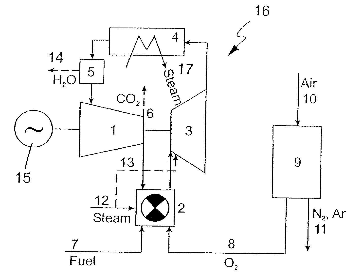
[0026] The compressor 1 and the turbine 3 of the gas turbine plant from FIG. 1 have the internal construction illustrated in simplified form in FIG. 5, the high-pressure side (the outlet side in the case of the compressor 1 and the inlet side in the case of the turbine 3) being located on the left side of the illustration. The compressor 1 and the turbine 3 have a rotor 18 rotatable about an axis 23 and having a multistage blading which consists of individual sets of moving blades 21. The rotor 18 with the blading is surrounded by a casing 19. Between the sets of moving blades 21 are arranged in each case fixed guide blade cascades 20 with corresponding guide blades. Flow ducts 22 run between the guide blades of the guide blade cascades 20 in the interspace of the rotor 18 and casing 19 (see also FIG. 6a).

[0027] According to the invention, then, the rotor 18 and casing 19 of a compressor 1 designed for air as the working medium and / or of a turbine 3 designed for air as the working ...


PUM


Abstract

A gas turbine plant with a compressor, a combustion chamber, a turbine and at least one heat sink is operated with a working medium in the form of a carbon dioxide / water mixture. A hydrocarbon reacts as fuel with oxygen in the combustion chamber, and the excess carbon dioxide and water thereby occurring is tapped from the circuit. The compressor and the turbine have in each case a rotor with moving blades and a casing with flow ducts and with guide blade cascades. In the compressor and / or the turbine, matching to the expansion behavior of the working medium, which is different from that of air, is brought about by modifications of the flow ducts, of the moving blades and / or of the guide blade cascades.

Description

CROSS-REFERENCE TO RELATED APPLICATIONS [0001] This application is a divisional of prior U.S. patent application Ser. No. 10 / 806,225 filed Mar. 23, 2004, which is a continuation of the U.S. National Stage designation of co-pending International Patent Application PCT / IB02 / 03912 filed Sep. 23, 2002, and the entire contents of these prior applications are expressly incorporated herein by reference thereto.FIELD OF THE INVENTION [0002] The present invention relates to the field of technology of gas turbines. It refers to a gas turbine plant for a working medium in the form of a carbon dioxide / water mixture. BACKGROUND OF THE INVENTION [0003] The prior art discloses gas turbine plants that operate in a circuit with a working medium in the form of a carbon dioxide / water mixture and are distinguished in that they allow the combustion of hydrocarbon-containing fuels, without carbon dioxide being discharged into the atmosphere. Such a gas turbine plant is described, for example, in the publ...

Claims


Application Information

Patent Timeline
Patent Type & Authority Applications(United States)
IPC IPC(8): F02C7/00F01D17/12F02C1/10F02C6/18
CPCF01D17/12F02C6/18F02C1/105
Inventor FRUTSCHI, HANS ULRICHGRIFFIN, TIMOTHYSPAN, ROLANDWINKLER, DIETER
Owner ALSTOM TECH LTD
Why Eureka
Try Eureka