Humidity detecting apparatus and vehicular air conditioner having the same

a technology of humidity detection and air conditioner, which is applied in the direction of humidity control, refrigeration components, digital computer details, etc., can solve the problems of increasing the cost of glass temperature detection except for contact detection using the temperature sensor, and the likely influence of glass temperature detection accuracy, so as to reduce ventilation heat loss, improve heat conduction, and accurately detect the effect of temperatur

Active Publication Date: 2008-03-20
DENSO CORP
View PDF5 Cites 40 Cited by
  • Summary
  • Abstract
  • Description
  • Claims
  • Application Information

AI Technical Summary

Benefits of technology

[0011]Since the heat conductive member is disposed between the window glass and the glass temperature sensor, the heat conductive member absorbs stress that will be caused when the humidity detecting apparatus is mounted to the window glass. For example, even when the sensors are soldered to a circuit board, it is less likely that soldering portions and the circuit board will be affected by the stress. Further, in a case that the glass temperature sensor is in pressed contact with the heat conductive member, heat conduction improves at contact surfaces between the glass temperature sensor and the heat conductive member. As such, the temperature of the window glass is accurately detected.
[0012]For example, the humidity detecting apparatus is employed to an air conditioner for a vehicle. The air conditioner has an inside / outside air switching device operable to open and close an inside air suction port and an outside air suction port for switching an air suction mode, a blower for blowing air drawn through at least one of the inside air suction port and the outside air suction port, a plurality of blowing-out openings for blowing air, a temperature of which has been controlled through at least one of the cooling heat exchanger and the heating heat exchanger, a blowing-out mode door operable to open and close at least a defroster blowing-out opening of the plurality of blowing-out openings for controlling an air blowing-out mode, in order to perform an air conditioning operation of a passenger compartment of the vehicle. The humidity detecting apparatus is disposed on an inner surface of a windshield of the vehicle. At least one of the inside / outside air switching device, the blower and the air blowing-out mode door is controlled based on the relative humidity calculated by the glass surface relative humidity calculation unit. Accordingly, the air conditioning operation, in particular, an anti-fog control operation is automatically performed based on the glass surface relative humidity detected by the humidity detecting apparatus. For example, the air suction mode is controlled such that an inside air ratio increases within a range without causing fog on the windshield. Thus, ventilation heat loss reduces, and hence a heating performance improves.

Problems solved by technology

However, the above discussed glass temperature detections except for the contact detection using the temperature sensor are likely to increase costs.
Further, detection accuracy of the glass temperature is likely to be affected by contact structure between the glass surface and the temperature sensor.

Method used


Image

  • Humidity detecting apparatus and vehicular air conditioner having the same
  • Humidity detecting apparatus and vehicular air conditioner having the same
  • Humidity detecting apparatus and vehicular air conditioner having the same

Examples


first embodiment

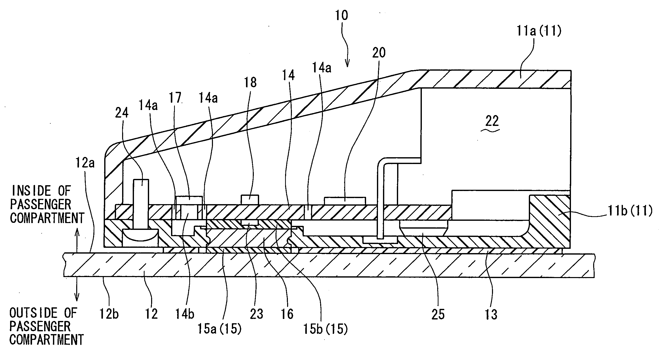
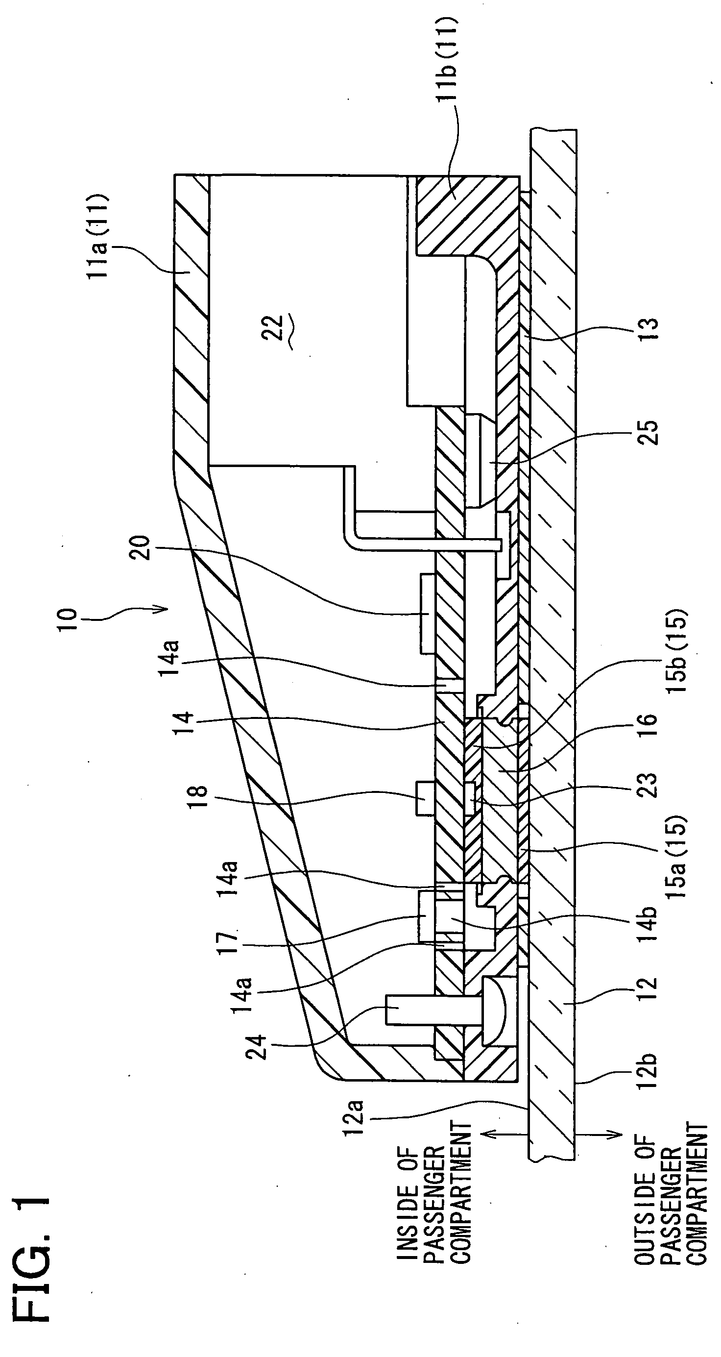
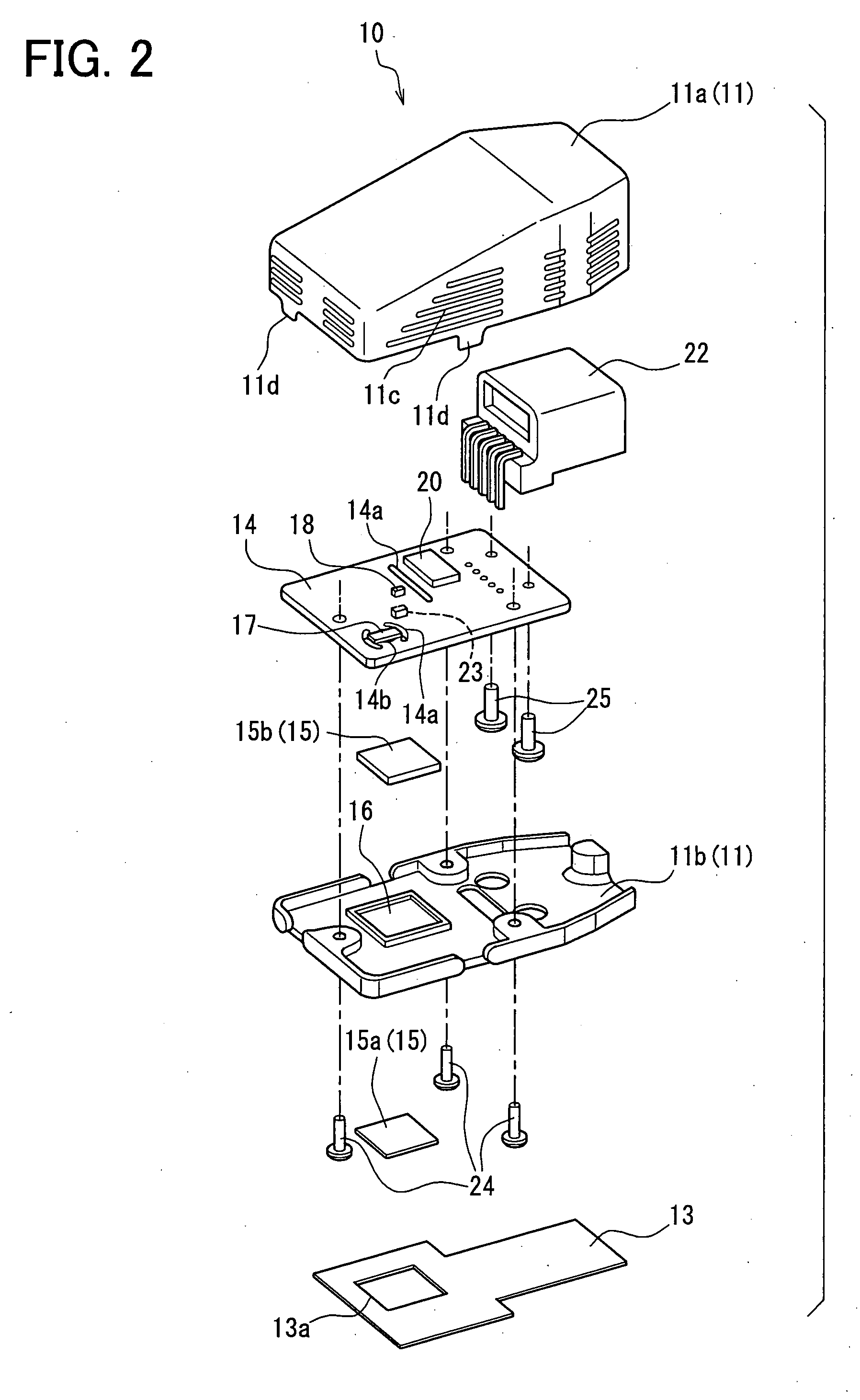
[0031]A first embodiment of the present invention will be described with reference to FIGS. 1 to 14. A humidity detecting apparatus 10 shown in FIGS. 1 and 2 is used, for example, for a vehicular air conditioner shown in FIG. 4.

[0032]First, a structure of the humidity detecting apparatus 10 will be described. As shown in FIGS. 1 and 2, the humidity detection apparatus 10 includes a case 11, which is, for example, made of a resin. The case 11 has a substantially flat, rectangular parallelepiped shape, and includes an upper case member 11a and a lower case member 11b. The upper case member 11a is formed with ventilation slits 11c on its side walls for allowing ambient air where the case 11 is disposed, such as air inside of a passenger compartment, to flow through the case 11.

[0033]The case 11 is fixed to an inner surface 12a of a window glass 12 of the vehicle through an adhesive sheet 13. For example, the window glass 12 is a front windshield of the vehicle, and the humidity detecti...

second embodiment

[0133]Next, a second embodiment of the present invention will be described with reference to FIG. 15. FIG. 15 shows a glass temperature detecting part of a humidity detecting apparatus 10 of the second embodiment. Hereafter, like components are denoted by like reference numerals as the first embodiment and a description thereof will not be repeated. Different structures and effects will be mainly described hereafter.

[0134]In the second embodiment, the glass temperature sensor 23 is not arranged on the circuit board 14 on which the humidity sensor 17 and the air temperature sensor 18 are mounted. As shown in FIG. 15, the glass temperature sensor 23 is connected to the circuit board 14 through electrically conductive members 23a.

[0135]For example, the metallic member 16 is divided into a first metallic part 16a and a second metallic part 16b. The glass temperature sensor 23 is arranged between the first metallic part 16a and the second metallic part 16b. The electrically conductive m...

third embodiment

[0139]Next, a third embodiment will be described with reference to FIG. 16. FIG. 16 shows a glass temperature detecting part of a humidity detecting apparatus 10 of the third embodiment. Hereafter, like components are denoted by like reference numerals as the first embodiment and a description thereof will not be repeated. Different structures and effects will be mainly described hereafter.

[0140]In the third embodiment, the glass temperature sensor 23 is arranged at a position separate from the circuit board 14 on which the humidity sensor 17 and the air temperature sensor 18 are mounted. As shown in FIG. 16, the glass-side heat conductive member 15a and the sensor-side heat conductive member 15b are disposed on the opposite sides of the metallic member 16. The sensor-side heat conductive member 15b has a thickness such that at least a temperature detecting portion of the glass temperature sensor 23 is embedded therein. For example, the sensor-side heat conductive member 15b is made...


PUM


Abstract

A humidity detecting apparatus includes a humidity sensor for detecting a relative humidity of air on an inner side of a window glass, an air temperature sensor for detecting a temperature of the air, a glass temperature sensor for detecting a temperature of the window glass, and a glass surface relative humidity calculation unit for calculating a glass surface relative humidity based on output values of the humidity sensor, the air temperature sensor and the glass temperature sensor. A heat conductive member is disposed between the glass temperature sensor and the window glass.

Description

CROSS REFERENCE TO RELATED APPLICATION[0001]This application is based on Japanese Patent Applications No. 2006-251561 filed on Sep. 15, 2006 and No. 2007-132077 filed on May 17, 2007, the disclosures of which are incorporated herein by reference.FIELD OF THE INVENTION[0002]The present invention relates to a humidity detecting apparatus and an air conditioner for a vehicle having the same.BACKGROUND OF THE INVENTION[0003]Generally, window fog detecting apparatuses for vehicles are mainly classified into a humidity detection type and an optical type. In the window fog detecting apparatus of the humidity detection type, for example, window fog is estimated by comparing a glass temperature with a dew-point temperature of ambient air thereof. The dew-point temperature is calculated based on outputs of a humidity sensor and an air temperature sensor, which are arranged in a passenger compartment of a vehicle.[0004]The glass temperature is detected by various methods, such as a contact det...

Claims


Application Information

Patent Timeline
Patent Type & Authority Applications(United States)
IPC IPC(8): F25D21/06F25D21/02G05D22/02
CPCB60H1/00785G05D23/19G01N25/56B60H1/00821
Inventor AOKI, SHINJIHIRAI, SHINICHIROUKATAOKA, TAKUYASUZUKI, YOSHIAKI
Owner DENSO CORP
Why Eureka
Try Eureka