Ultrasonic transducer driving circuit and ultrasonic diagnostic apparatus

a technology of ultrasonic transducer and driving circuit, which is applied in the direction of mechanical vibration separation, pulse technique, instruments, etc., can solve the problems of increasing power consumption and circuit size, and achieve the effects of suppressing power consumption, reducing circuit size, and suppressing power consumption

Inactive Publication Date: 2008-03-20
GE MEDICAL SYST GLOBAL TECH CO LLC
View PDF6 Cites 23 Cited by
  • Summary
  • Abstract
  • Description
  • Claims
  • Application Information

AI Technical Summary

Benefits of technology

[0010]In the ultrasonic transducer driving circuit according to the above first aspect, after the positive field effect transistor is turned on in accordance with the positive pulse signal, at the time of rise to a predetermined positive voltage, the positive field effect transistor is turned off; therefore, the output voltage to the ultrasonic transducer rises, but is restricted up to the predetermined positive voltage. Then, the output voltage to the ultrasonic transducer can be returned to the ground voltage by the ground clamp circuit. Thus, both the voltage value and the pulse width of a positive pulse that is applied to the ultrasonic transducer can be controlled. Also, after the negative field effect transistor is turned on in accordance with the negative pulse signal, at the time of fall to a predetermined negative voltage, the negative field effect transistor is turned off; therefore, the output voltage to the ultrasonic transducer falls, but is restricted down to the predetermined negative voltage. Then, the output voltage to the ultrasonic transducer can be returned to the ground voltage by the ground clamp circuit. Thus, both the voltage value and the pulse width of a negative pulse that is applied to the ultrasonic transducer can be controlled. Because each FET is turned off when the output voltage to the ultrasonic transducer goes up to a predetermined voltage or goes down to a predetermined voltage, power consumption can be suppressed. Because there is no need for supply voltage switching circuits for the FETs, circuit size can be reduced.
[0026]The ultrasonic transducer driving circuit and the ultrasonic diagnostic apparatus of the present invention can be utilized to improve the performance of ultrasonic diagnostic apparatus and reduce the size thereof.

Problems solved by technology

However, each FET remains on as long as a pulse width duration when a pulse of a voltage is applied to the ultrasonic transducer and this posed a problem of an increase in power consumption.
However, since a supply voltage switching circuit for each FET is a power supply circuit, a problem that the circuit size becomes larger emerged.

Method used


Image

  • Ultrasonic transducer driving circuit and ultrasonic diagnostic apparatus
  • Ultrasonic transducer driving circuit and ultrasonic diagnostic apparatus
  • Ultrasonic transducer driving circuit and ultrasonic diagnostic apparatus

Examples


embodiment 1

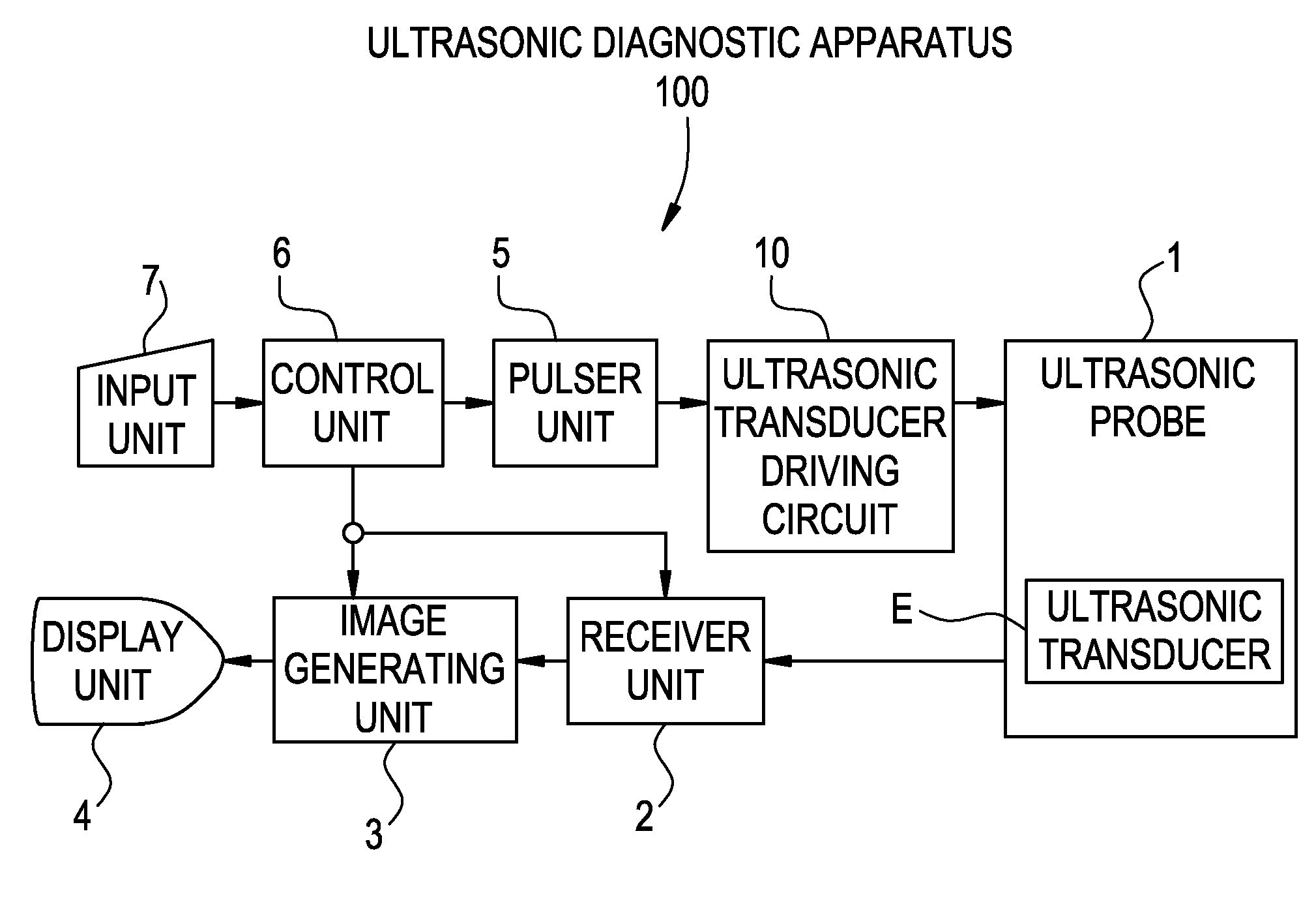
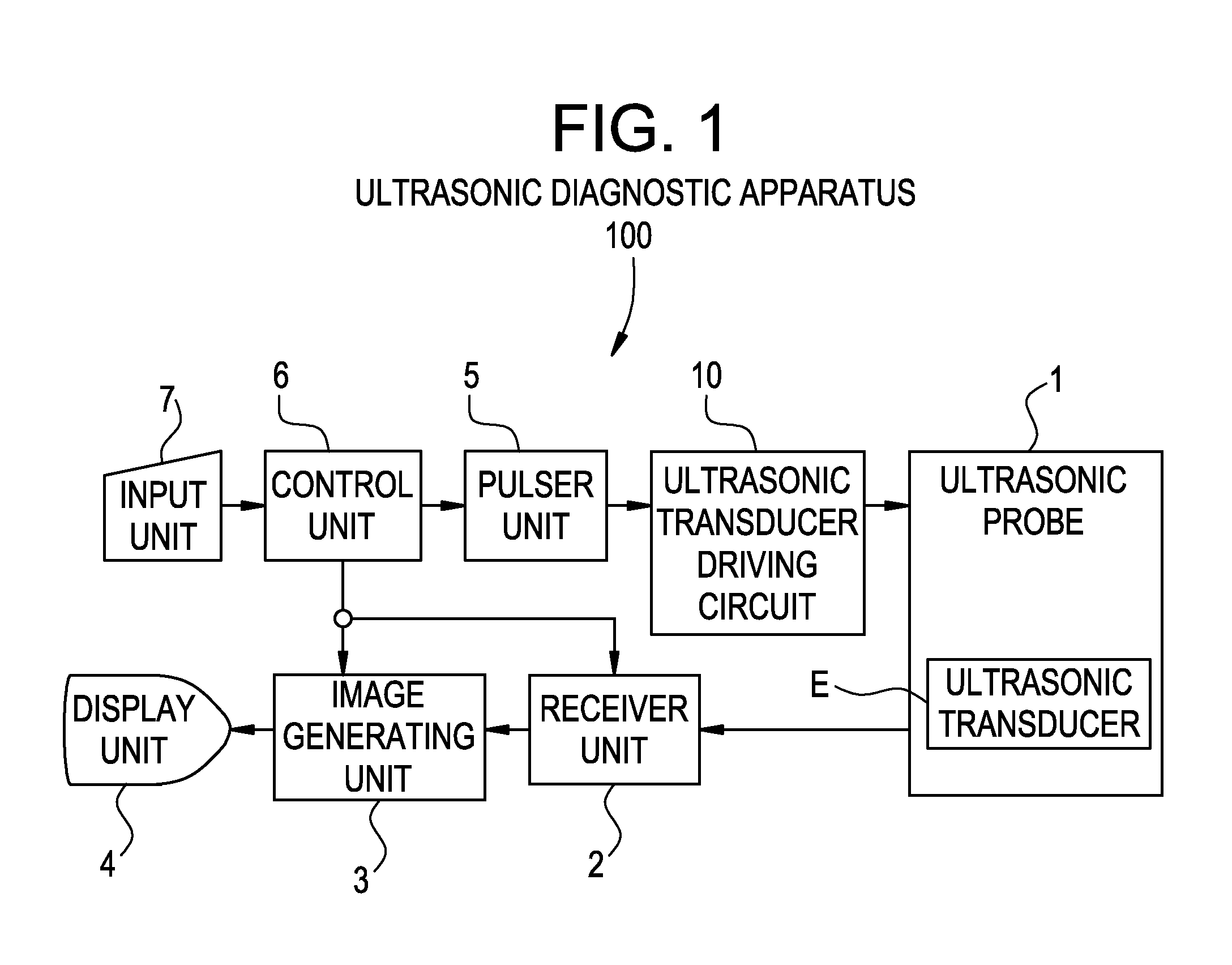
[0033]FIG. 1 is a structural diagram showing an ultrasonic diagnostic apparatus 100 relevant to Embodiment 1.

[0034]This ultrasonic diagnostic apparatus 100 includes: an ultrasonic probe 1 within which multiple ultrasonic transducers E are installed and which transmits ultrasonic beams from the transducers into a specimen body and receives ultrasonic echoes from within the specimen body; a receiver unit 2 which generates and outputs an acoustic beam signal from the ultrasonic echoes; an image generating unit 3 which generates an ultrasonic image based on the acoustic beam signal; a display unit 4 which displays the ultrasonic image; an ultrasonic transducer driving circuit 10 which drives the ultrasonic transducer E for transmitting the ultrasonic pulses; a pulser unit 5 which inputs a signal for transmission to the ultrasonic transducer driving circuit 10; a control unit 6 which takes overall control of the apparatus; and an input unit 7 which is used for an operator to operate the ...

embodiment 2

[0050]The present invention can be applied in the same manner as for Embodiment 1, when a predetermined negative voltage is applied to the ultrasonic transducer E, followed by a return to the ground voltage and application of a predetermined positive voltage, and even when the predetermined negative voltage is applied to the ultrasonic transducer E, followed by application of the predetermined positive voltage.


PUM

PropertyMeasurementUnit
voltageaaaaaaaaaa
ground voltageaaaaaaaaaa
positive thresholdaaaaaaaaaa

Abstract

With the aim of suppressing power consumption and reducing circuit size, a positive FET is turned on in accordance with a positive pulse signal and turned off when a return voltage rises up to a positive threshold. An active ground clamp circuit causes the output line to return to the ground voltage after the elapse of a predetermined period of time. A negative FET is turned on in accordance with a negative pulse signal and turned off when the return voltage falls down to a negative threshold. The active ground clamp circuit causes the output line to return to the ground voltage after the elapse of a predetermined period of time.

Description

BACKGROUND OF THE INVENTION[0001]The present invention relates to an ultrasonic transducer driving circuit and an ultrasonic diagnostic apparatus and, more particularly, relates to an ultrasonic transducer driving circuit and an ultrasonic diagnostic apparatus that can suppress power consumption and allow for a reduction in circuit size.[0002]Heretofore, there is known an ultrasonic diagnostic apparatus including a positive FET (Field Effect Transistor) which outputs a positive voltage onto an output line to an ultrasonic transducer at on state, a negative FET which outputs a negative voltage onto the output line to the ultrasonic transducer, and a driver circuit which drives the positive FET and the negative FET (e.g., see Patent Document 1 and Patent Document 2).[0003][Patent Document 1] Japanese Unexamined Patent Publication No. 2006-101997 (FIG. 10, FIG. 12, FIG. 14)[0004][Patent Document 2] Japanese Unexamined Patent Publication No. 2004-358133 (FIG. 2)[0005]In the above ultras...

Claims


Application Information

Patent Timeline
Patent Type & Authority Applications(United States)
IPC IPC(8): G01N29/00H03K17/687
CPCA61B8/00A61B2560/0209B06B1/0207H03K17/6872B06B2201/76H03K17/284B06B2201/55G01N29/24
Inventor AMEMIYA, SHINICHI
Owner GE MEDICAL SYST GLOBAL TECH CO LLC
Why Eureka
Try Eureka