Induction air acoustics management for internal combustion engine

a technology of internal combustion engine and induction air, which is applied in the direction of machines/engines, non-mechanical valves, output power, etc., can solve the problems of difficult control at lower manifold vacuums and low to moderate engine speeds, inability to provide acceptable acoustic control of manifold pressure using feedback and/or feed-forward control based on manifold pressure, etc., to achieve the effect of reducing intake noise and increasing intake vacuum

Inactive Publication Date: 2008-03-20
FORD GLOBAL TECH LLC
View PDF7 Cites 35 Cited by
  • Summary
  • Abstract
  • Description
  • Claims
  • Application Information

AI Technical Summary

Benefits of technology

[0007]Those of ordinary skill in the art will recognize a number of advantages associated with the present disclosure. For example, a more robust control that estimates induction acoustics based on an intake airflow sensor and manages acoustics by appropriate positioning of the throttle valve or other actuator to selectively increase intake vacuum and reduce intake noise under various engine / vehicle operating conditions is provided. Furthermore, induction acoustics management is provided using existing sensors and actuators rather than relying on additional acoustic or vibration sensors.

Problems solved by technology

However, this often increases sound levels associated with induction air that may exceed some customer's expectations under various operating conditions and may therefore be undesirable.
However, this solution depends on the particular throttle body flow characteristics and provides acceptable results at moderate manifold vacuums, but is difficult to control at lower manifold vacuums and low to moderate engine speeds, particularly in variable displacement engines that may operate on fewer than all of the cylinders with active cylinders operating at full load.
Under these conditions controlling the throttle to a target manifold pressure using feedback and / or feed-forward control based on manifold pressure does not provide acceptable acoustic control because small throttle valve angle changes can increase induction sound levels without a corresponding increase in manifold pressure.

Method used


Image

  • Induction air acoustics management for internal combustion engine
  • Induction air acoustics management for internal combustion engine
  • Induction air acoustics management for internal combustion engine

Examples


Embodiment Construction

)

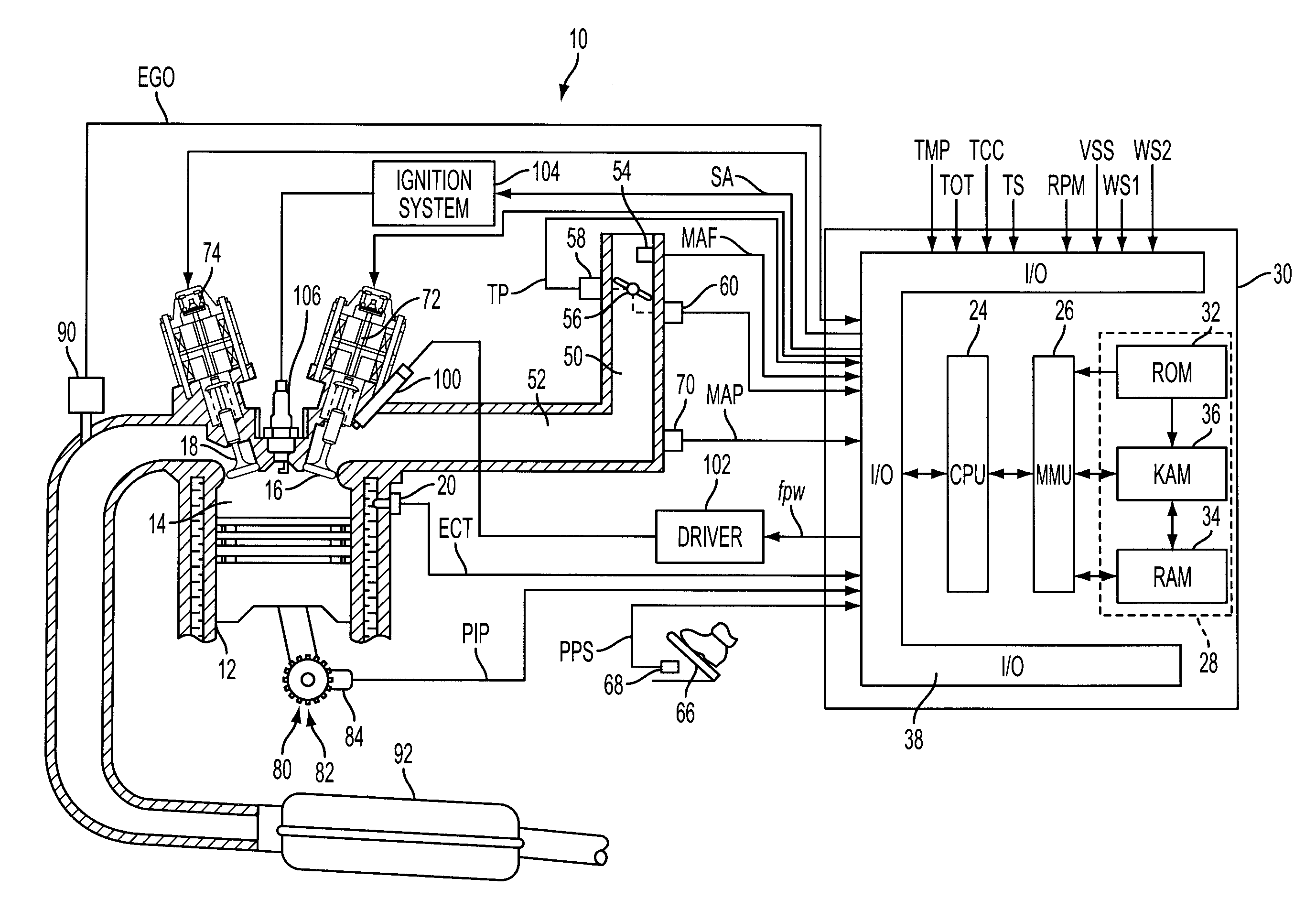
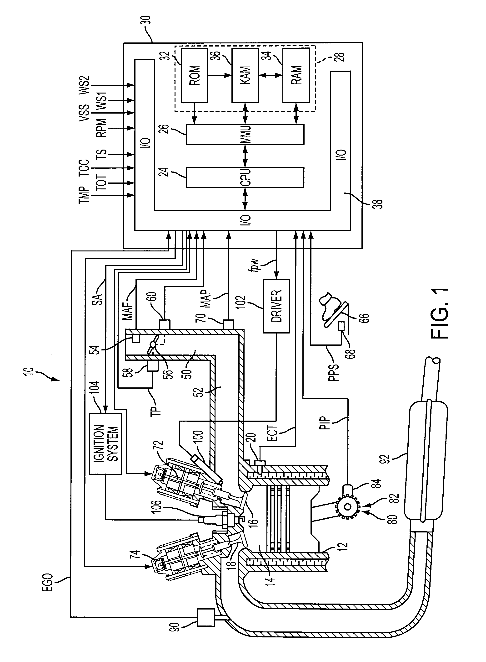
[0011]As those of ordinary skill in the art will understand, various features of the embodiments illustrated and described with reference to any one of the Figures may be combined with features illustrated in one or more other Figures to produce alternative embodiments that are not explicitly illustrated or described. The combinations of features illustrated provide representative embodiments for typical applications. However, various combinations and modifications of the features consistent with the teachings of the present disclosure may be desired for particular applications or implementations. The representative embodiments used in the illustrations relate generally to a four-stroke, multi-cylinder port injected internal combustion engine operable in a variable displacement mode with electromagnetically actuated intake and / or exhaust valves and an electronically controlled throttle valve. Those of ordinary skill in the art may recognize similar applications or implementations w...


PUM


Abstract

A system and method for controlling an internal combustion engine control an actuator in response to variations of intake airflow relative to an average intake airflow to manage induction acoustics. The system and method may include controlling an actuator, such as a throttle valve, to increase intake manifold vacuum in response to intake airflow. In an engine having electronically actuated intake and / or exhaust valves, intake airflow is estimated based on at least engine speed and valve timing and compared to a measured intake airflow to determine a first difference. The measured airflow is divided into a steady-state and transient term or component with a second difference determined based on the transient component and a target value. Throttle valve position is selectively controlled to increase vacuum in response to a combination of the first and second difference to manage induction acoustics.

Description

BACKGROUND[0001]1. Technical Field[0002]Systems and methods for controlling an internal combustion engine to manage induction air acoustics.[0003]2. Background Art[0004]Customer expectations for engine / vehicle sounds generally vary based on the type of vehicle and relative engine / vehicle output, with louder sounds expected or tolerated at higher engine outputs. Internal combustion engine valve train technologies developed to improve fuel economy, such as electromagnetic valve actuation (EVA), can control airflow by changing valve timing and opening the electronic throttle valve to reduce pumping losses and increase engine efficiency. However, this often increases sound levels associated with induction air that may exceed some customer's expectations under various operating conditions and may therefore be undesirable. One known strategy used to manage acoustics associated with induction air includes closing the electronic throttle in response to a manifold pressure (MAP) sensor to cr...

Claims


Application Information

Patent Timeline
Patent Type & Authority Applications(United States)
IPC IPC(8): F01L9/04F01L9/20
CPCF01L9/04Y02T10/18F02D13/0253Y02T10/12F01L9/20
Inventor MICHELINI, JOHNKOLMANOVSKY, ILYA
Owner FORD GLOBAL TECH LLC
Why Eureka
Try Eureka