Reducing intake manifold pressure during cranking

A technology of intake manifold pressure and engine, applied in the direction of brakes, electrical control, electrical components, etc., can solve the problems of reducing fuel economy emissions, difficult engine cold start, ineffective evaporation, etc., to reduce cold start exhaust emissions, provide fuel economy benefits, and demand-reducing effects

Inactive Publication Date: 2013-10-30
FORD GLOBAL TECH LLC
View PDF8 Cites 10 Cited by
  • Summary
  • Abstract
  • Description
  • Claims
  • Application Information

AI Technical Summary

Problems solved by technology

However, alcohols and alcohol-based fuels are less volatile than gasoline and therefore may not evaporate efficiently at typical engine starting temperatures and pressures
Therefore, engine starts using alcohol and alcohol-based fuels, especially cold engine starts, can be difficult
Further, incomplete evaporation of fuel can reduce fuel economy and reduce emissions

Method used


Image

  • Reducing intake manifold pressure during cranking
  • Reducing intake manifold pressure during cranking
  • Reducing intake manifold pressure during cranking

Examples


Embodiment Construction

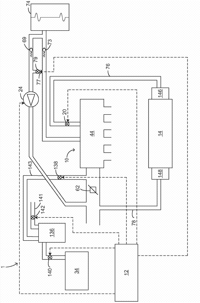
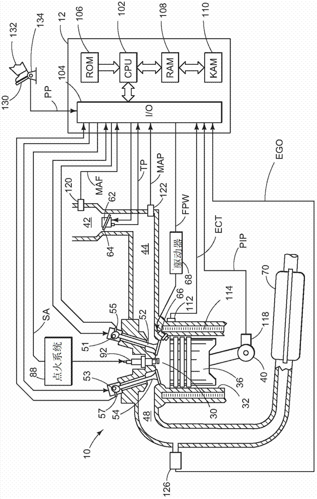
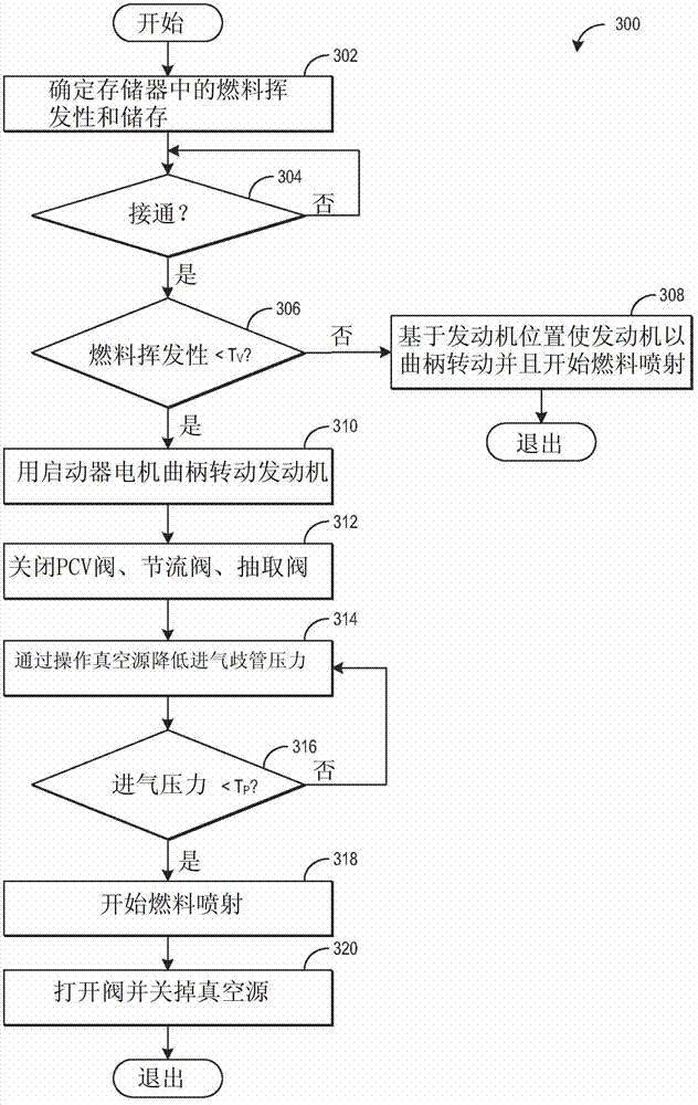
[0027] Low volatility fuels such as ethanol and ethanol-gasoline blends may not evaporate as efficiently as gasoline under typical engine start conditions. As a result, fuel economy and emissions may be reduced, and engine cold starts may be unreliable. To increase evaporation of low volatility fuels, intake manifold vacuum may be increased during cranking via a vacuum source, such as a vacuum pump, connected to the intake manifold. Further, one or more controllable valves connected to the intake manifold, such as a throttle valve and a PCV valve, may be commanded closed to ensure rapid pump down of the intake manifold. Intake manifold vacuum can increase to a critical level, at which point fuel injection can begin. The critical level of vacuum may be proportional to the volatility of the injected fuel. figure 1 and 2 is an example engine diagram that includes the fuel injection system, vacuum pump, electronic PCV valve, and image 3 controller with the method shown in . ...


PUM


Abstract

Embodiments for starting an engine are provided. In one embodiment, an engine control method comprises, during engine cranking, commencing fuel injection when intake manifold pressure drops below a threshold, the threshold based on fuel volatility. In this way, the stability of engine starts using low volatility fuels may be increased.

Description

technical field [0001] The present disclosure relates to starting an internal combustion engine. Background technique [0002] Alternative fuels have been developed to mitigate the rising price of traditional fuels, to reduce dependence on imported fuels, and to reduce the generation of emissions such as CO2. For example, alcohols and alcohol-based fuel blends have been recognized as attractive alternative fuels, especially for automotive applications. However, alcohols and alcohol-based fuels are less volatile than gasoline, and thus may not evaporate efficiently at typical engine starting temperatures and pressures. Therefore, engine starting using alcohol and alcohol-based fuels, especially cold engine starting, can be difficult. Further, incomplete evaporation of fuel may reduce fuel economy and reduce emissions. Contents of the invention [0003] The present inventors have recognized the above problems and provided a solution to at least partly address these proble...

Claims


Application Information

Patent Timeline
Patent Type & Authority Applications(China)
IPC IPC(8): F02D43/00F02D41/30B60T13/46F01M13/00
CPCF02D41/30F02D43/00F02D2200/0406F02D19/084F02D41/06F02M35/10229F02D2200/0611B60T13/46F02D13/0207F02D41/064F02M25/089F02D41/0025F02D2009/0249F02D13/0219F02D2009/024F01M13/00B60T17/02F01M13/023F01M2013/0066H04N21/23424H04N21/44016H04N21/47202H04N21/8451H04N21/8456H04N19/61H04N19/70Y02T10/30H04N21/2665H04N21/812H04N19/44H04N19/46
Inventor T·G·莱昂内R·D·皮尔西弗
Owner FORD GLOBAL TECH LLC
Why Eureka
Try Eureka