Sealing Means for a Closure, Closure and Process

a technology of sealing means and closures, applied in the direction of closure lids, closure stoppers, caps, etc., can solve the problems of less hard and less durable materials, distorted sealing lip, and poor lateral adjustment of sealing lips, so as to achieve the effect of ensuring lateral/radial flexibility

Active Publication Date: 2008-03-20
CREANOVA UNIVERSAL CLOSURES
View PDF49 Cites 45 Cited by
  • Summary
  • Abstract
  • Description
  • Claims
  • Application Information

AI Technical Summary

Benefits of technology

[0020] The toroidal sealing ring comprises a protrusion which is arranged in engaged position towards the neck of the container and defines a contact zone. In difference to seals known form prior art which are mainly subject to annular pressure or bending forces in the root, the in general perpendicularly freestanding sealing means according to the present invention mainly seals due to annular tension forces occurring in the toroidal sealing ring when applied onto the neck of a container. The sealing means is designed such that it is capable to adjust / compensate a certain amount of lateral and / or radial offset or distortion of the neck of the container. The cylindrical skirt, which acts as the base, provides a certain flexibility in lateral / radial direction. Good results are achieved in that the proportion ratio vertical length to radial thickness of the base of the sealing means, which is arranged between the top portion of the closure and the toroidal sealing ring, is at least 1:1 preferably 4:1. Depending on the field of application further aspect ratios are relevant such as the radial thickness and shape of the base of the sealing means and the radial thickness of the annular sealing ring and the aspect ratio of the vertical length to the radial thickness of the annular sealing ring and the gap between the inner and the outer skirt.

Problems solved by technology

The latter is mainly used for the manufacture of liner closures; the material is less hard and less durable than PE.
However, due to the obliged arrangement of the sealing lip the sealing lip often tends to be distorted during application, especially crooked application onto a neck of a container.
A further disadvantage consists in that due to the inclined arrangement this seal is relatively rigid and therefore not very good in adjusting in lateral direction.
One disadvantage is that the described deformation of the closure is related to extensive operating forces.
A further disadvantage consists in that the outer shell tends to break due to extensive stress and deformation (stress cracking) which results in complete failure of the closure and loss of the product.
One disadvantage consists in the reduced lateral adjustability.
One disadvantage of the described procedure is that displacement of the core can only take place when the material of the first stage has sufficiently congealed which results in a significant delay.
A further disadvantage consists in that the geometry of the closure and the seal is significantly restricted due to the mould function.
A still further disadvantage is that the seal may not comprise a radial protrusion which would result in an undercut the mould because displacement of the mould core would not be possible anymore.
A problem of closures known from prior art is that the seal of these closures often fails at high internal pressure and content leaks due to doming or lift-off of the top portion of the cap.
Especially with caps which seal primarily on the inner peripheral surface or on the annular top surface of the neck of the container this problem may occur.
A further problem often occurring with closures known from prior art is leakage of the seal due to high internal pressure in the container and additional top load applied to the top of the closure, e.g. due to stacking of several containers.
A further problem of the closures known from prior art is that the seal fails due to crooked application of the closure onto a neck of a container.

Method used


Image

  • Sealing Means for a Closure, Closure and Process
  • Sealing Means for a Closure, Closure and Process
  • Sealing Means for a Closure, Closure and Process

Examples


Embodiment Construction

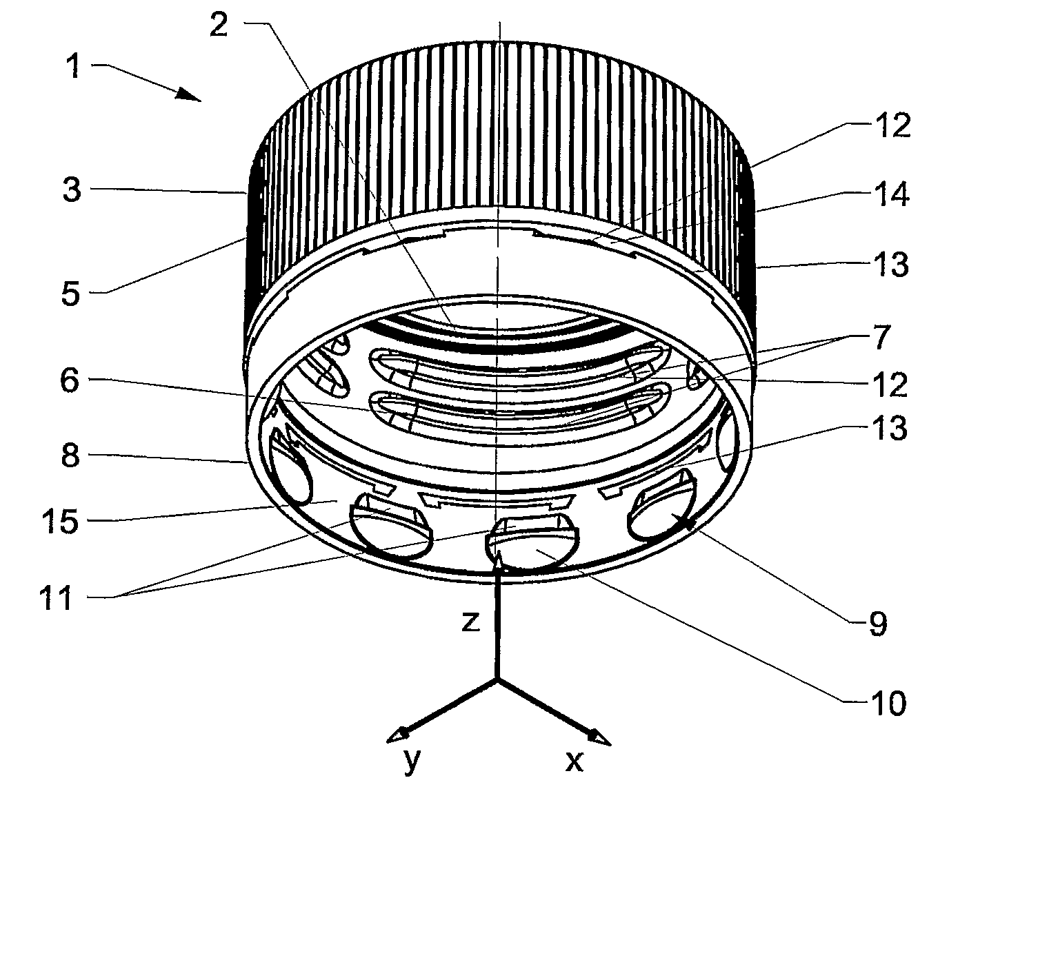
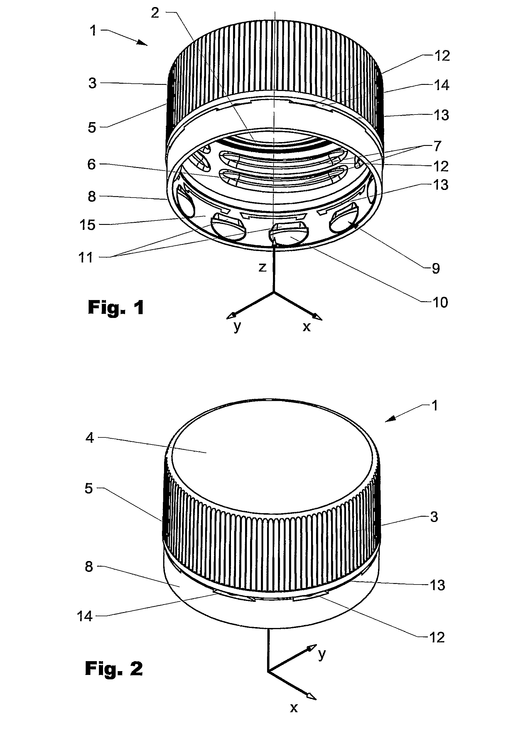
[0042]FIG. 1 is showing a closure 1 comprising a sealing means 2 according to the present invention in an isometric side view from below and FIG. 2 the same closure 1 from a perspective side view from above. The closure 1 comprises an outer skirt 3 extending in general perpendicular from a disc-like top portion 4. The outer skirt 3 has on its outside vertically arranged knurls 5 which provide a better grip while operating the closure. On the inside the outer skirt 3 comprises a thread 6 consisting of thread segments 7. At its lower end the outer skirt is interconnected to a tamper band 8. The tamper band 8 of the displayed embodiment has in general the same outer diameter as the outer skirt 3 of the closure. On its inside the tamper band 8 comprises undercut segments 9 protruding radially inwardly and having a in general spherical lower part 10. During application of the closure onto the neck of a container (not visible) the spherical undercut segments support centering and alignmen...


PUM


Abstract

The present invention is directed to a sealing means for sealing of a neck of a container, especially a container for carbonated beverages. The sealing means comprises a radially deformable outer sealing means suitable to be engaged with an outer free surface of a neck of the container. The outer sealing means comprises an annular base which blends by a blend into a vertical top surface and at least one annular sealing ring arranged at a free end of the annular base, protruding radially inwardly above the inner surface of the base and forming in engaged position with the neck a first contact area with the outer free surface.

Description

FIELD OF THE INVENTION [0001] The invention relates to a sealing means for closures, especially sealing means for closures for packages for liquids such as beverages. In particular the invention relates to a sealing means for containers for carbonated liquids such as soft drinks but is well adapted to seal other containers such as glass or PET containers with contents at above or below atmospheric pressure or having gaseous components or requiring a hermetic seal. The invention further relates to a closure and a process for making and applying of a sealing means, respectively a closure. BACKGROUND OF THE INVENTION [0002] Seals of closures are generally manufactured from several types of plastic, such as Polyethylene (from now on PE) or Polypropylene (from now on PP) or EVA-based materials such as Darex™ liner material. The latter is mainly used for the manufacture of liner closures; the material is less hard and less durable than PE. Softer material such as Low density PE (LDPE), et...

Claims


Application Information

Patent Timeline
Patent Type & Authority Applications(United States)
IPC IPC(8): B65D41/00
CPCB65D41/04B65D41/3447B65D41/045
Inventor DRUITT, RODNEY
Owner CREANOVA UNIVERSAL CLOSURES
Why Eureka
Try Eureka