Electric driving machine

Inactive Publication Date: 2008-03-20
HITACHI KOKI CO LTD
View PDF9 Cites 27 Cited by
  • Summary
  • Abstract
  • Description
  • Claims
  • Application Information

AI Technical Summary

Benefits of technology

[0024] According to the present invention, even when a battery voltage of the battery pack has caused a transient decrease at the time of startup of the motor that drives the flywheel, the power terminal and the reset terminal of the control means are replenished with a normal voltage by the voltage

Problems solved by technology

However, the pneumatic driving machine suffers a problem of workability being impaired by the hose which supplies compressed air to the driving machine from the air compressor and which always accompanying the driving machine.
Further, a heavy air compressor must be carried in conjunction with the pneumatic driving machine, and hence great inconvenience is encountered in moving and installing the air compressor.
However, the present inventors have found that, when a single battery pack is used as the power source for driving the motor and the controller, it may be the case where a sufficient source voltage cannot be supplied to the controller at startup of the motor

Method used


Image

  • Electric driving machine
  • Electric driving machine
  • Electric driving machine

Examples


Example

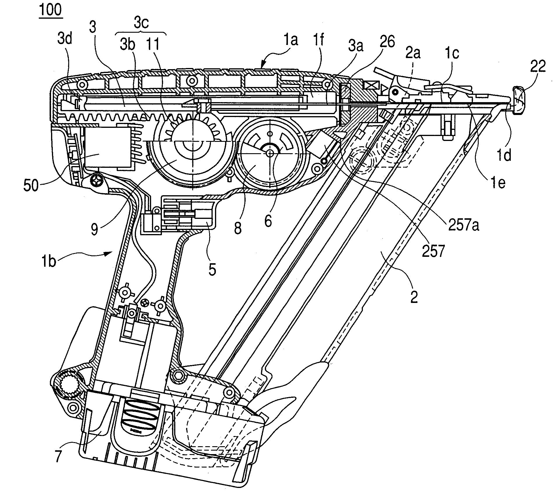
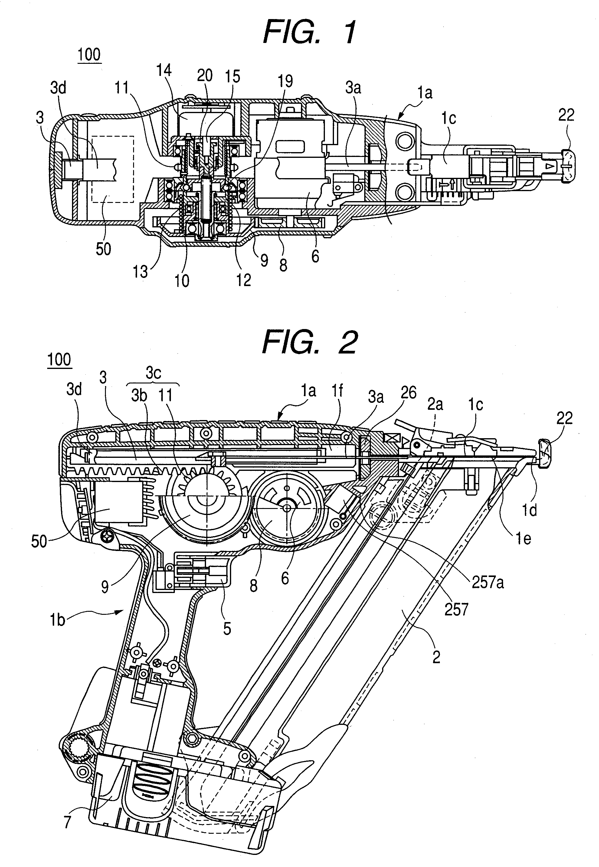
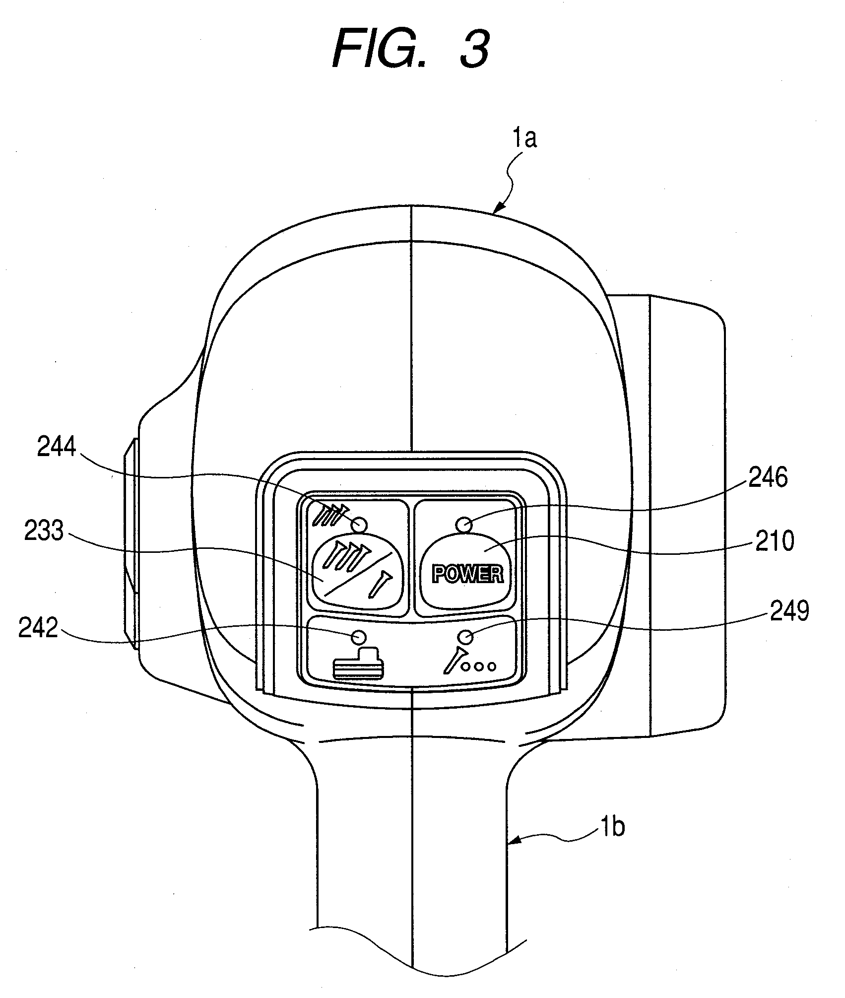
[0051] An embodiment in which the present invention is applied to an electric driving machine will be described hereunder by reference to the drawings. In addition to including descriptions of characteristics of the present invention, the following descriptions of an embodiment encompass descriptions of characteristics of other inventions in order to facilitate comprehension of the configuration and advantages of an overall electric driving machine of the present embodiment. Throughout the drawings for explanation of the embodiment, members having the same functions are assigned the same reference numerals, and their repeated explanations are omitted.

[0052] [Built-Up Structure of an Electric Driving Machine]

[0053] A built-up structure of an electric driving machine of the embodiment of the present invention will first be described by reference to FIGS. 1 through 8.

[0054] As shown in a top view of FIG. 1 and a side view of FIG. 2, an electric driving machine 100 comprises a main bo...


PUM

PropertyMeasurementUnit
Electric potential / voltageaaaaaaaaaa
Energyaaaaaaaaaa

Abstract

Even when a transient decrease has arisen in a battery voltage VBAT of a battery pack at startup of a motor that drives a flywheel, a power terminal Vcc and a reset terminal RES (or an input terminal IN of a reset IC) of a microcomputer are replenished with a normal voltage by the voltage accumulated by a capacitor of the backup power circuit, and hence a controller can maintain normal operation without involvement of faulty operation. As a result, even the battery pack whose battery has a smaller amount of remaining energy can be effectively utilized as the power source of an electric driving machine.

Description

CROSS-REFERENCE TO RELATED APPLICATIONS [0001] This application is based on and claims the benefit of priority from the prior Japanese Patent Application No. 2006-248897, filed on Sep. 14, 2006; the entire contents of which are incorporated herein by reference. TECHNICAL FIELD [0002] The present invention relates to an electric driving machine which uses a motor as a driving drive source for driving a fastener, such as nails, staples, and the like. The present invention relates particularly to an electric driving machine including a power transmission mechanism—which has a clutch mechanism for transmitting rotational drive force of a motor in the electric driving machine, as rectilinear drive force, to an actuator having a drive blade for driving the fastener—and a controller for controlling operation timing of the motor. BACKGROUND Description of the Related Art [0003] A pneumatic driving machine—which guides air compressed by an air compressor through use of an air hose and uses t...

Claims


Application Information

Patent Timeline
IPC IPC(8): B25C5/15B25C5/00
CPCB25C1/06
Inventor SHIMA, YUKIHIROINANIWA, MASAHIROODA, HIROYUKIUEDA, TAKASHINAKANO, YOSHIHIRO
Owner HITACHI KOKI CO LTD
Why Eureka
Try Eureka