Distributed Optical Fiber Sensor

a technology of optical fiber and optical fiber, applied in the direction of instruments, heat measurement, force measurement, etc., can solve the problems of poor strain measurement accuracy and wider width of optical pulses

Active Publication Date: 2008-03-20
NEUBREX
View PDF5 Cites 83 Cited by
  • Summary
  • Abstract
  • Description
  • Claims
  • Application Information

AI Technical Summary

Benefits of technology

[0088] Accordingly, in the case of using the intensity-stepwise optical pulse OPs having the respective time widths set as above, the ratio Prx of the intensity-stepwise optical pulse OPs may be set within the range where H2 / (H1+H3+H4) is about 0.5 or larger for the detection of strain and / or temperature with high accuracy and high spatial resolution and may be set at the value where H2 / (H1+H3+H4) reaches the peak for the detection of strain and / or temperature with highest accuracy and highest spatial resolution.
[0089] From the above description, it can be understood to determine the respective time widths Tf, Tp, Tb of the intensity-stepwise optical pulse OPs within the aforementioned ranges, to simulate H2 / (H1+H3+H4) in relation to the ratio Prx defined by Equation 12 in the intensity-stepwise optical pulse OPs having these determined time widths Tf, Tp, Tb in accordance with Equations 8 to 11, and to set the ratio Prx of the intensity-stepwise optical pulse at such a value where H2 / (H1+H3+H4) is 0.5 or larger, particularly at a value where H2 / (H1+H3+H4) reaches the peak in order to detect strain and / or temperature with high accuracy and high spatial resolution and to detect a change of a minute strain. Further, the usable minimum length of the sensing optical fiber SOF can be specified based on the intensity-stepwise optical pulse OPs having the determined time widths Tf, Tp, Tb.

Problems solved by technology

Thus, the spatial resolution Δz becomes about 2 to 3 m. Although the optical pulse having a short width is necessary to improve the spatial resolution, the spectral width of the optical pulse becomes wider in this case, with the result that strain measurement accuracy becomes poor.

Method used


Image

  • Distributed Optical Fiber Sensor
  • Distributed Optical Fiber Sensor
  • Distributed Optical Fiber Sensor

Examples


first embodiment

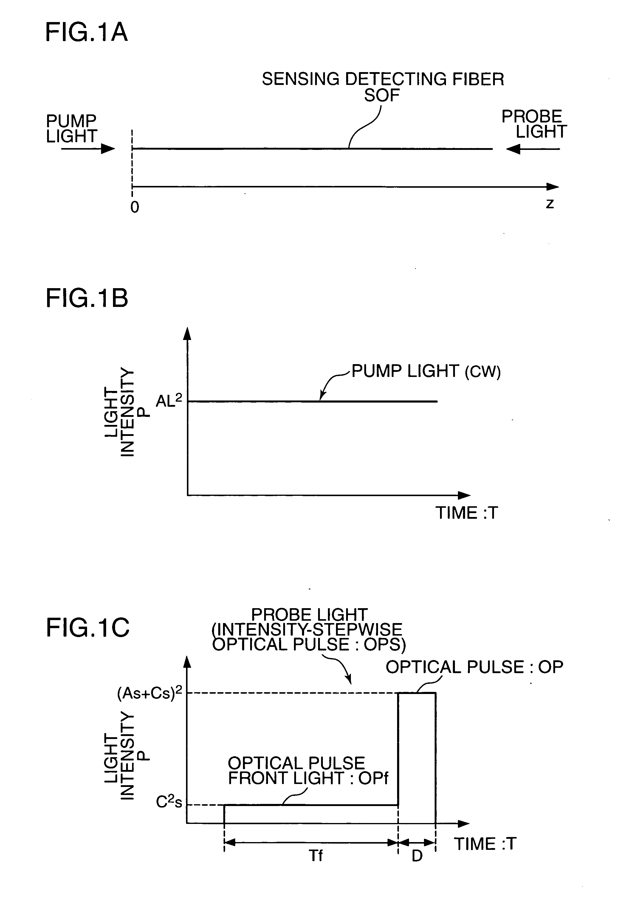
[0091] A distributed optical fiber sensor according to a first embodiment of the present invention is for detecting a strain and / or temperature distribution based on a Brillouin frequency shift by causing an intensity-stepwise optical pulse as probe light to be incident on one end of a sensing optical fiber for detecting strain and / or temperature and causing a continuous light as pump light to be incident on the other end of this sensing optical fiber to receive light attributed to a Brillouin scattering phenomenon occurred in the sensing optical fiber, and by conducting a Brillouin gain spectrum time domain analysis (BGain-OTDA) or a Brillouin loss spectrum time domain analysis (BLoss-OTDA). Hereinafter, the Brillouin gain spectrum time domain analysis and the Brillouin loss spectrum time domain analysis are abbreviated as Brillouin loss / gain spectrum time domain analyses. In this Brillouin loss / gain spectrum time domain analysis, the light attributed to the Brillouin scattering ph...

second embodiment

[0171] A distributed optical fiber sensor according to a second embodiment of the present invention is for detecting strain and / or temperature based on Brillouin frequency shifts by causing a probe light and a pump light to be incident on one end of a sensing optical fiber for detecting strains and / or temperatures, receiving the pump light subjected to the action of a Brillouin scattering phenomenon in the sensing optical fiber, and applying a Brillouin gain spectrum time domain reflection analysis (BGain-OTDR, Brillouin gain optical time domain reflectometer) or a Brillouin loss spectrum time domain reflection analysis (BLoss-OTDR, Brillouin loss optical time domain reflectometer). Hereinafter, the Brillouin gain spectrum time domain reflection analysis or the Brillouin loss spectrum time domain reflection analysis is abbreviated as a Brillouin loss / gain spectrum time domain reflection analysis. In this Brillouin loss / gain spectrum time domain reflection analysis, light attributed ...

third embodiment

[0191] A distributed optical fiber sensor according to a third embodiment of the present invention can singly apply a Brillouin gain spectrum time domain reflection analysis and a Brillouin loss spectrum time domain reflection analysis.

[0192] First, the distributed optical fiber sensor according to the third embodiment is described. FIG. 17 is a block diagram showing the construction of the distributed optical fiber sensor according to the third embodiment.

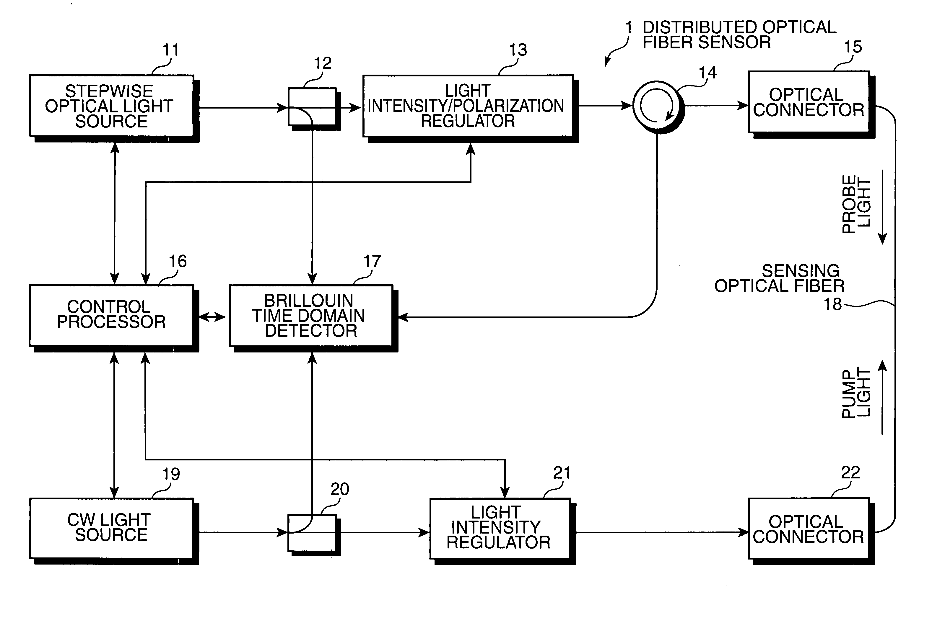
[0193] In FIG. 17, the distributed optical fiber sensor 3 according to the third embodiment is provided with a stepwise optical light source 11, an optical coupler 12, a light intensity / polarization regulator 13, an optical circulator 14, an optical coupler 33, an optical connector 15, a control processor 41, a Brillouin time domain detector 17, a sensing optical fiber 18, a CW light source 32, an optical coupler 20, a light intensity regulator 21, an optical switch 42 and an optical connector 22.

[0194] An output terminal of th...


PUM


Abstract

A distributed optical fiber sensor uses a Brillouin scattering phenomenon to avoid manual adjustment and to measure strain and / or temperature with high accuracy and high spatial resolution. A stepwise optical light source generates an optical pulse having a stepwise distribution of intensity to increase toward the center, and a continuous light source generates continuous light on. The optical pulse is incident on a sensing optical fiber as probe light and the continuous light is incident as pump light to cause a Brillouin scattering phenomenon between the probe light and the pump light. A Brillouin time domain detector determines a Brillouin loss or gain spectrum from the light emerging from the sensing optical fiber and attributed to the Brillouin scattering phenomenon, and measures strain in and / or temperature of the sensing optical fiber in the longitudinal direction thereof based on the determined Brillouin loss or gain spectrum.

Description

BACKGROUND OF THE INVENTION [0001] 1. Field of the Invention [0002] The present invention relates to a distributed optical fiber sensor capable of measuring strain and / or temperature in longitudinal direction with high accuracy and high spatial resolution using an optical fiber as a sensor. [0003] 2. Description of the Related Art [0004] A method based on a Brillouin scattering phenomenon occurring in an optical fiber is known as a technology for measuring strains and temperatures. In this method, the optical fiber is used as a medium for detecting strain and / or temperature in an environment where the optical fiber is placed. [0005] The Brillouin scattering phenomenon is such a phenomenon that, when two light rays having different frequencies pass each other in an optical fiber, power transfers via acoustic phonons in the optical fiber from the light having a higher frequency to the one having a lower frequency. If νd denotes a frequency difference between two light waves passing ea...

Claims


Application Information

Patent Timeline
Patent Type & Authority Applications(United States)
IPC IPC(8): G01B11/16
CPCG01B11/18G01D5/35364G01L1/242G01K11/32
Inventor KISHIDA, KINZOLI, TEKKENLIN, SHENBIN
Owner NEUBREX
Why Eureka
Try Eureka