Actuator, optical scanner, and image forming apparatus

a technology of optical scanner and image forming device, which is applied in the direction of dynamo-electric machines, instruments, and electric armatures with armatures. it can solve the problems of increasing production cost and power consumption, and achieve the effects of reducing the distance between the coil, promoting power-saving and size reduction, and increasing the deflection angl

Active Publication Date: 2008-03-20
SEIKO EPSON CORP
View PDF2 Cites 7 Cited by
  • Summary
  • Abstract
  • Description
  • Claims
  • Application Information

AI Technical Summary

Benefits of technology

[0008]An advantage of the invention is to provide an actuator, an optical scanner, and an image-forming device that each allow an increase in deflection angle while promoting power-saving and size reduction.
[0009]According to a first aspect of the invention, an actuator includes a frame-shaped first mass portion; a supporting portion that supports the first mass portion and takes the shape of a frame so as to surround a perimeter of the first mass portion; a pair of first elastic portions coupling between the first mass portion and the supporting portion so that the first mass portion is supported by the supporting portion; a second mass portion provided inside the frame-shaped first mass portion; a pair of second elastic portions coupling between the second mass portion and the first mass portion so that the second mass portion is supported by the first mass portion; and a driver for rotating the first mass portion. The driver includes a ferromagnet provided on the first mass portion in a position separate from a rotation central axis of the first mass portion; a coil formed along the rotation central axis of the first mass portion and the supporting portion so as to surround and orbit a perimeter of the ferromagnet if the first mass portion is seen from above; and a voltage application unit for applying a voltage to the coil. An operation of the voltage application unit included in the driver causes the coil to generate a magnetic field. The generation of the magnetic field causes displacement of the ferromagnet relative to the coil. The displacement of the ferromagnet causes the first mass portion to rotate while torsionally deforming the pair of first elastic portions. The rotation of the first mass portion causes the second mass portion to rotate while torsionally deforming the pair of second elastic portions.
[0010]This allows a reduction in the distance between the coil and the ferromagnet without preventing rotation of the first mass portion. Thus the rotation angle (deflection angle) of the first mass portion is increased while promoting size reduction and power-saving of the actuator, thereby eventually increasing the rotation angle (deflection angle) of the second mass portion.
[0011]In the actuator according to the first aspect of the invention, the ferromagnet is preferably mainly made of a soft magnetic material.
[0012]This allows selection from a wider range of materials, thereby increasing freedom in designing.
[0013]In the actuator according to the first aspect of the invention, the voltage application unit is preferably configured to intermittently apply a direct current to the coil.

Problems solved by technology

This results in an increase in power consumption.
This requires alignment when these components are mounted, resulting in an increase in production cost.

Method used


Image

  • Actuator, optical scanner, and image forming apparatus
  • Actuator, optical scanner, and image forming apparatus
  • Actuator, optical scanner, and image forming apparatus

Examples


first embodiment

[0042]A first embodiment of the invention will be described below.

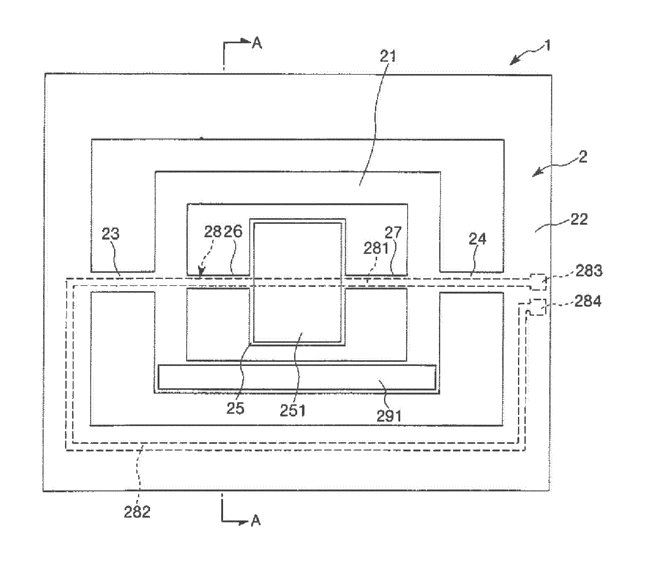
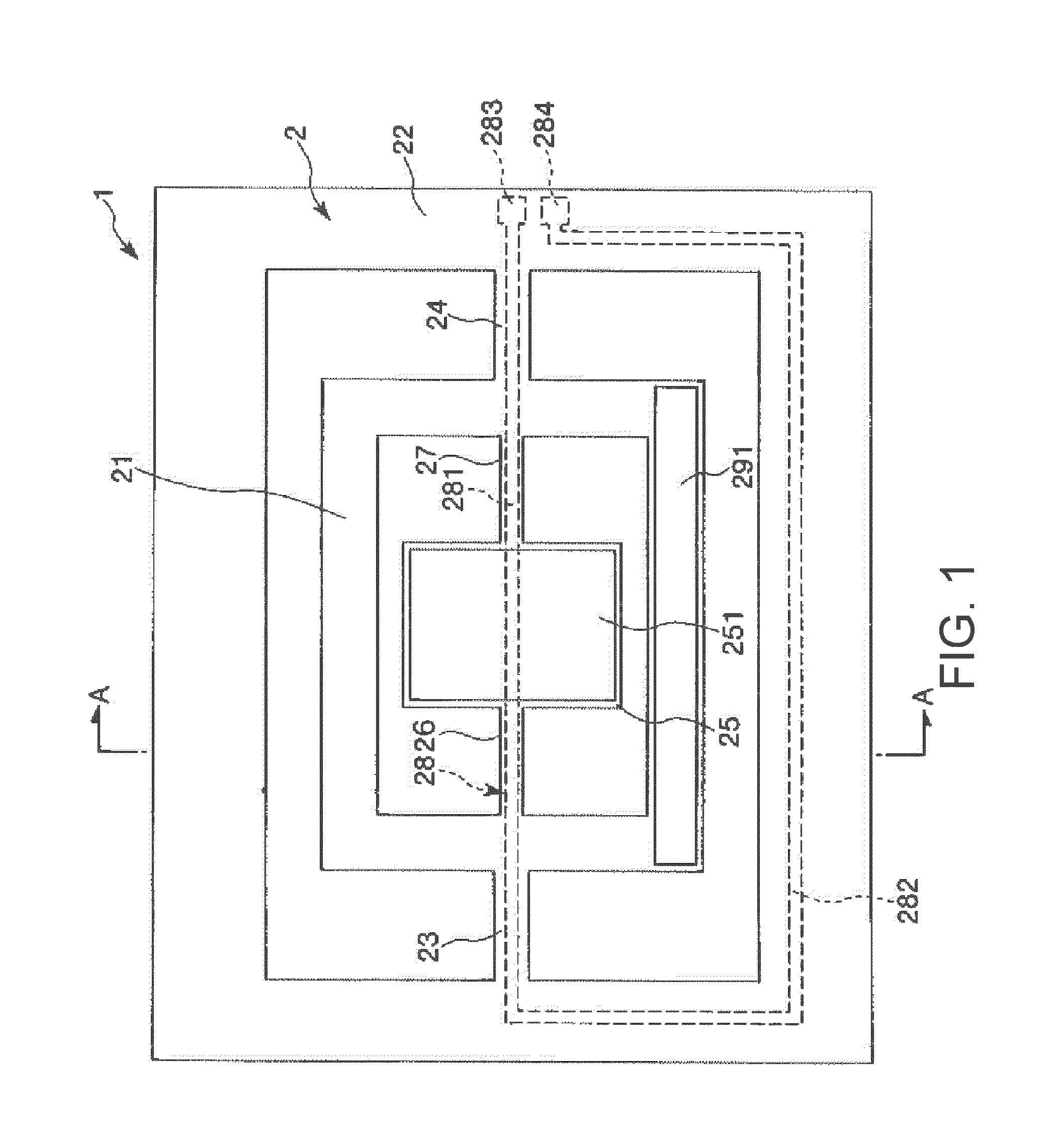
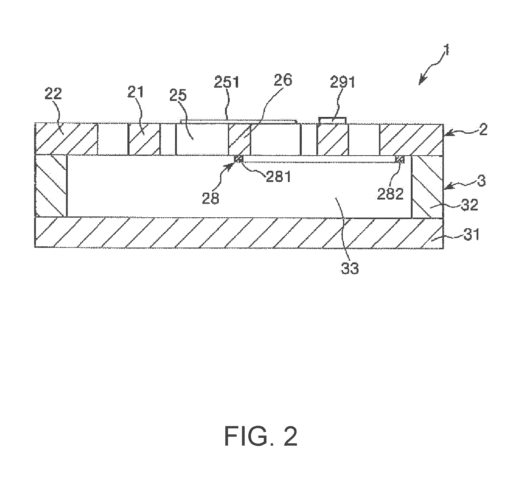
[0043]FIG. 1 is a plan view showing an actuator according to the first embodiment of the invention. FIG. 2 is a sectional view taken along line A-A of FIG. 1. FIG. 3 is a diagram showing a coil included in the actuator shown in FIG. 1. FIG. 4 is a graph showing the relations between the amplitudes of a first mass portion and a second mass portion and the frequency of an applied voltage, of the actuator shown in FIG. 1.

[0044]In FIG. 1, the direction from the paper surface toward the viewer will be referred to as “upper,” the direction from the paper surface toward the back as “lower,” the right direction as “right,” and the left direction as “left” for the sake of convenience. In FIG. 2, the upper direction will be referred to as “upper,” and the lower direction as “lower,” the right direction as “right,” and the left direction as “left.”

[0045]An actuator 1 shown in FIGS. 1 and 2 includes a base 2 having a two-degree-o...

second embodiment

[0096]An actuator according to a second embodiment of the invention will now be described.

[0097]FIG. 5 is a plan view showing the actuator according to the second embodiment of the invention. FIG. 6 is a sectional view taken along line A-A of FIG. 5.

[0098]With regard to the actuator according to the second embodiment, description will be focused on the differences between the actuators according to the second and first embodiments and similar matters will not be described.

[0099]As shown in FIGS. 5 and 6, an actuator 1A according to the second embodiment is approximately similar to the first embodiment except that its coil shape and power supply circuit configuration are different from those of the actuator according to the first embodiment.

[0100]As shown in FIGS. 5 and 6, in the actuator 1A according to the second embodiment, the coil 28A is formed along the rotation central axis X and the supporting portion 22 so that a coil 28A is symmetrical to the rotation central axis X when se...


PUM

PropertyMeasurementUnit
thicknessaaaaaaaaaa
thicknessaaaaaaaaaa
massaaaaaaaaaa

Abstract

An actuator includes a frame-shaped first mass portion; a supporting portion that supports the first mass portion and takes the shape of a frame so as to surround a perimeter of the first mass portion; a pair of first elastic portions coupling between the first mass portion and the supporting portion so that the first mass portion is supported by the supporting portion; a second mass portion provided inside the frame-shaped first mass portion; a pair of second elastic portions coupling between the second mass portion and the first mass portion so that the second mass portion is supported by the first mass portion; and a driver for rotating the first mass portion. The driver includes a ferromagnet provided on the first mass portion in a position separate from a rotation central axis of the first mass portion; a coil formed along the rotation central axis of the first mass portion and the supporting portion so as to surround and orbit a perimeter of the ferromagnet if the first mass portion is seen from above; and a voltage application unit for applying a voltage to the coil. An operation of the voltage application unit included in the driver causes the coil to generate a magnetic field. The generation of the magnetic field causes displacement of the ferromagnet relative to the coil. The displacement of the ferromagnet causes the first mass portion to rotate while torsionally deforming the pair of first elastic portions. The rotation of the first mass portion causes the second mass portion to rotate while torsionally deforming the pair of second elastic portions.

Description

1. TECHNICAL FIELD[0001]The present invention relates to an actuator, an optical scanner, and an image-forming device.2. RELATED ART[0002]As optical scanners for forming images by performing an optical scan for use with a laser printer or the like, one using an actuator having a structure including a torsional vibrator for size reduction or other purposes is known (for example, see JP-A-06-175060).[0003]For example, an actuator according to JP-A-06-175060 includes a frame-shaped member, a pair of torsional springs for supporting the frame-shaped member from both sides, a plate-shaped member (reflection mirror) provided inside the frame-shaped member, and a pair of torsional springs for supporting the plate-shaped member from both sides relative to the frame-shaped member. These members constitute a two-degree-of-freedom vibration system. In the actuator, a structure including the above-mentioned vibration system is supported by a supporting board.[0004]The actuator also includes a p...

Claims


Application Information

Patent Timeline
Patent Type & Authority Applications(United States)
IPC IPC(8): H01F7/08G02B26/10
CPCG02B26/085G02B26/101H02K33/16H01F2007/068H02K33/02H01F7/14
Inventor MIZOGUCHI, YASUSHI
Owner SEIKO EPSON CORP
Why Eureka
Try Eureka