
Layered fire retardant barrier panel

a technology of fire retardant panels and fire retardant enclosures, which is applied in the field of layered phenolic resin-based fire retardant panels, can solve the problems of time-consuming and complicated methods of prior art in creating fire retardant panels and enclosures, and achieve the effect of enduring high temperatures

Inactive Publication Date: 2008-03-20
CURRAN WILLIAM F +1
View PDF3 Cites 26 Cited by
  • Summary
  • Abstract
  • Description
  • Claims
  • Application Information

AI Technical Summary

Benefits of technology

[0010] Another object is to provide an improved fire retardant panel that withstands high temperatures.
[0011] Another object is to provide an improved fire retardant panel for use in a fireproof safe or fireproof cabinet that can protect items inside the safe or cabinet from thermal damage.
[0013] Another object is to provide an improved fire retardant panel that effectively delays heat transfer from one side to the other.
[0015] Another object is to provide a simple method for manufacturing an improved fire retardant panel.

Problems solved by technology

Although phenolic resin is known for its fire-resistant properties, the methods of creating fire retardant panels and enclosures in the prior art are complicated and time consuming.

Method used


Image

  • Layered fire retardant barrier panel
  • Layered fire retardant barrier panel
  • Layered fire retardant barrier panel

Examples


Embodiment Construction

[0032] At the outset, it should be clearly understood that like reference numerals are intended to identify the same structural elements, portions or surfaces consistently throughout the several drawing figures, as such elements, portions or surfaces may be further described or explained by the entire written specification, of which this detailed description is an integral part. Unless otherwise indicated, the drawings are intended to be read (e.g., cross-hatching, arrangement of parts, proportion, degree, etc.) together with the specification, and are to be considered a portion of the entire written description of this invention. As used in the following description, the terms “horizontal”, “vertical”, “left”, “right”, “up” and “down”, as well as adjectival and adverbial derivatives thereof (e.g., “horizontally”, “rightwardly”, “upwardly”, etc.), simply refer to the orientation of the illustrated structure as the particular drawing figure faces the reader. Similarly, the terms “inw...


PUM

PropertyMeasurementUnit
pressureaaaaaaaaaa
thicknessaaaaaaaaaa
thickaaaaaaaaaa

Abstract

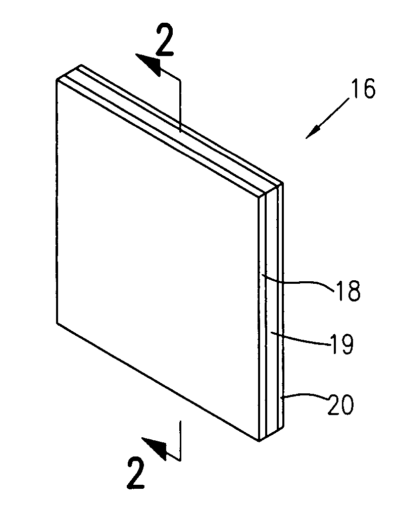
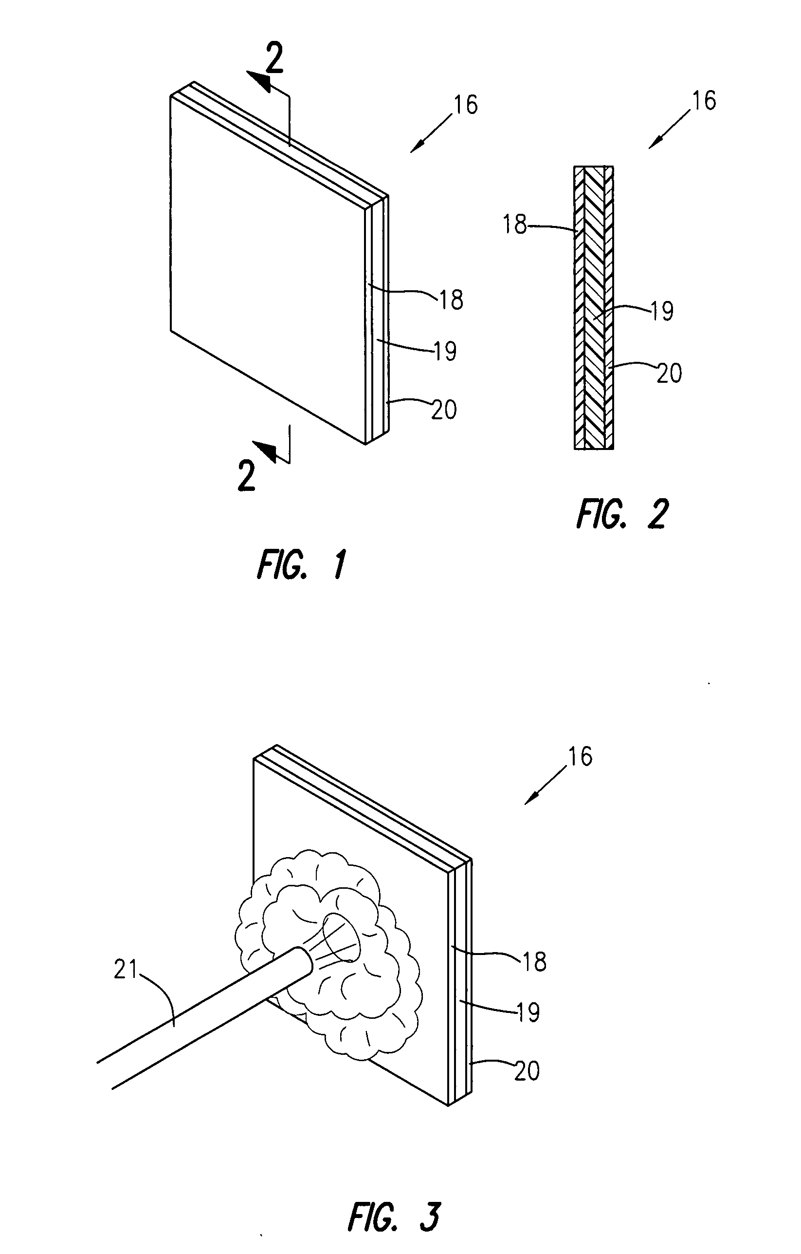
A fire retardant barrier panel (16) comprising a first protective layer (18) of a first material and a fire resistant phenolic-based resin layer (19) bonded to the protective layer. The first material may be selected from the group consisting of gypsum, ceramic fiber, phenolic foam, basalt, fiberglass, carbon fiber, mineral wool and intumescent materials. The resin may be a phenol or phenolic resin. The fire retardant barrier panel may further comprise a second protective layer (20) bonded to the resin layer (19) such that the resin layer is between the first and second protective layers. The second protective layer (20) may be selected from the group consisting of gypsum, ceramic fiber, phenolic foam, basalt, fiberglass, carbon fiber, mineral wool and intumescent materials.

Description

CROSS-REFERENCE TO RELATED APPLICATIONS [0001] This application claims the benefit of U.S. Provisional Patent Application No. 60 / 836,794, filed Aug. 10, 2006. The entire content of such application is incorporated by reference herein.TECHNICAL FIELD [0002] The present invention relates generally to fire retardant materials, and more particularly to a layered phenolic-resin-based fire retardant panel. BACKGROUND ART [0003] The use of phenolic resins for fire resistance is known in the prior art. For example, U.S. Pat. No. 5,079,078 discloses a fire resistant panel of woven glass preimpregnated with a phenolic resin. The panel is formed as a single layer by a compression molding technique that utilizes pressure of 50-100 psi at a temperature of 350 degrees for 20-30 minutes. U.S. Pat. No. 5,320,870 discloses a method of spraying phenolic resin compositions to form an outer fire protective coating. [0004] Phenolic-based resin panels are known in the prior art for uses other than fire p...

Claims


Application Information

Patent Timeline
Patent Type & Authority Applications(United States)
IPC IPC(8): B32B17/00B29C33/38B32B5/00C09K21/00
CPCB29C39/006B29C39/10B29C39/123Y10T428/254B32B19/04B32B27/42E04B1/942B32B17/02Y10T428/249928
Inventor CURRAN, WILLIAM F.RUNDLE, HUGH J.
Owner CURRAN WILLIAM F
Learn More