
Gasket, a bipolar battery and a method for manufacturing a gasket

a gasket and bipolar battery technology, applied in the direction of sustainable manufacturing/processing, nickel accumulators, cell components, etc., can solve the problems of difficult to achieve the proper combination of above characteristics in secondary (rechargeable) batteries, the design of starved electrolyte batteries is typically much less tolerant of electrolyte loss

Active Publication Date: 2008-03-20
NILAR INT AB
View PDF6 Cites 34 Cited by
  • Summary
  • Abstract
  • Description
  • Claims
  • Application Information

AI Technical Summary

Benefits of technology

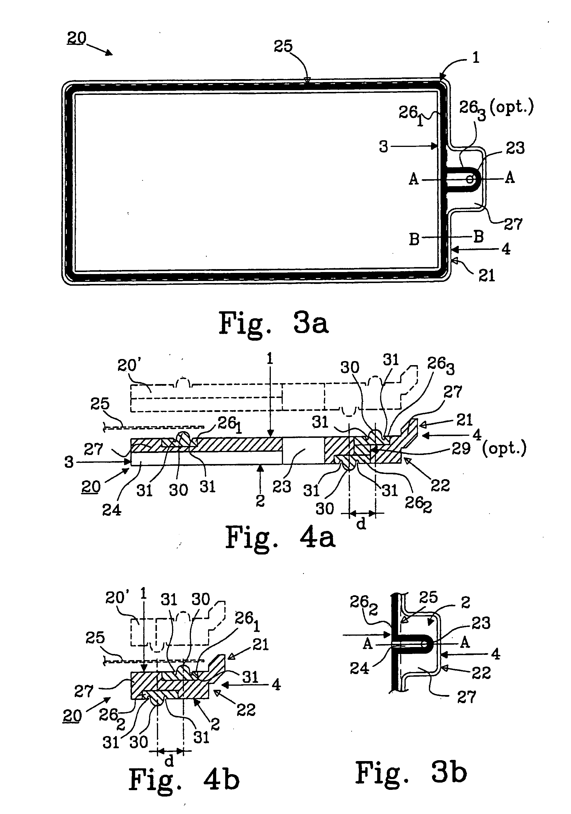
Example embodiments provide a gasket that reduces the mechanical preloaded force needed to maintain a sealed gas space and prevents wet electrolyte bridging that can allow ionic currents to flow between cells within a bipolar battery. The gasket has hydrophobic properties and is shaped like a frame with a more deformable material in the first part and a less deformable material in the second part. This results in a reduced required compressive force to maintain a seal. The use of a less rigid and lighter casing reduces the weight of the completed battery compared to prior art batteries. The stack of gaskets within a bipolar battery is more stable and achieves better seal uniformity. The more deformable part provides the sealing, resulting in better seal uniformity.

Problems solved by technology

The above characteristics are more difficult to achieve in secondary (rechargeable) batteries due to the charging potential that can generate gas inside the battery, and in alkaline batteries due to the creep nature of the electrolyte.
Achieving the proper combination of these characteristics has proven very difficult.
This results in a battery configuration that is essentially damp, but not flooded or wet inside the battery.
Starved electrolyte battery designs are typically much less tolerant of loss of electrolyte when compared to flooded batteries, as they have no extra wet reserve of electrolyte to compensate for electrolyte loss.
However, sealed bipolar designs typically utilize flat electrodes and stacked-cell constructions that present design challenges for proper containment of gases present and generated during cell operation.
The pressure-containment requirement creates additional challenges in the design of a stable bipolar configuration.
NiMH systems are seen as an alternative to meet cycle life specifications, but costs for existing conventional fabrication are too high.
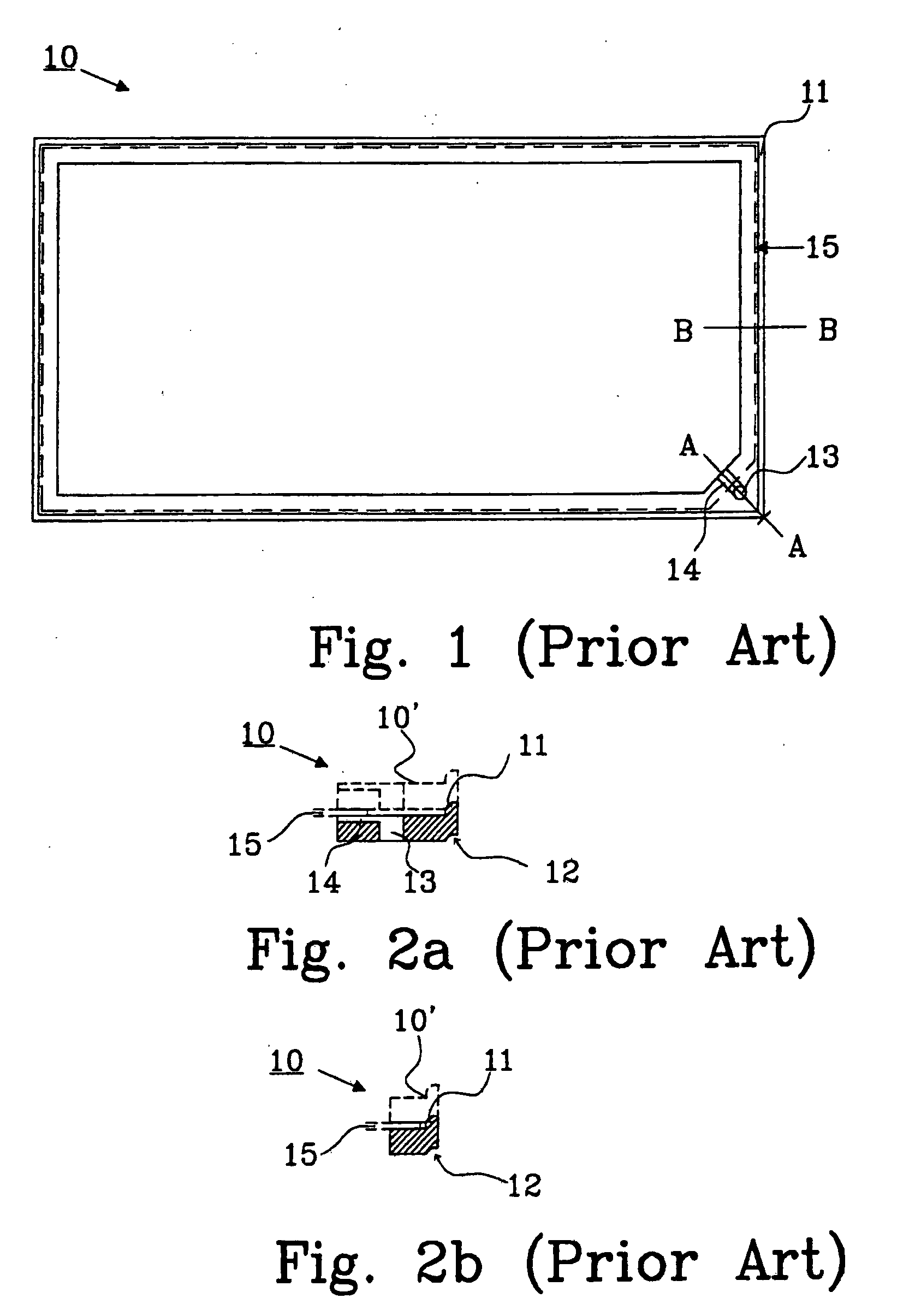
Although a problem with pressure differences between the cells may be avoided, there is still a disadvantage with the described battery.
The outer sealing around the edge of each biplate still has to be fluid-tight, which is very difficult to achieve.
Such encapsulation processes are expensive and difficult to accomplish in a reliable, manufacturable fashion.
As a result, large forces are needed to cause the required compressive strain in the disclosed frame necessary to induce a gas tight seal.
This large force must be borne by the structure of the battery, resulting in larger size, higher weight and increased cost of the resulting battery.
Rippel's disclosure also does not address the problem of ionic currents that may flow in the electrolyte present in the gas passages that can cause imbalanced self-discharge of individual bipolar electrodes in the battery.
Again, such a continuous encapsulation is expensive and more difficult to manufacture.
Wilson addresses the problem of reducing ionic currents that may flow in the electrolyte present in the gas passages by teaching use of a low conductivity electrolyte, which is clearly undesirable in a starved electrolyte secondary battery when high power density is desired.
It is however rather expensive to manufacture a bipolar battery of this design in large quantities and therefore there is a need to construct a new bipolar battery having a smaller quantity of components, using simpler processing techniques to manufacture a bipolar battery.

Method used


Image

  • Gasket, a bipolar battery and a method for manufacturing a gasket
  • Gasket, a bipolar battery and a method for manufacturing a gasket
  • Gasket, a bipolar battery and a method for manufacturing a gasket

Examples


Embodiment Construction

[0035] Benefits of the bipolar battery design include simplicity and low resistance losses. The parts count of the battery is relative low, and may consist only of endplates and biplates, with appropriate assembly of electrodes, separators and electrolyte and sealing components. Batteries of a desired voltage are constructed by stacking the required number of biplates. The electrical connections between the cells are made as the battery is stacked, since each biplate is electrically conductive and impervious to electrolyte.

[0036] With terminals at each end of the stack, the flow of current is perpendicular to the plate, which ensures uniform current and voltage distribution. Since the current path is very short the voltage drop is significantly reduced.

[0037] Bipolar batteries will also have significantly reduced weight, volume and manufacturing costs due to elimination of components and the manufacturing approach.

[0038] A problem with bipolar batteries is obtaining a reliable se...


PUM

PropertyMeasurementUnit
hydrophobic propertiesaaaaaaaaaa
elastic modulusaaaaaaaaaa
pressureaaaaaaaaaa

Abstract

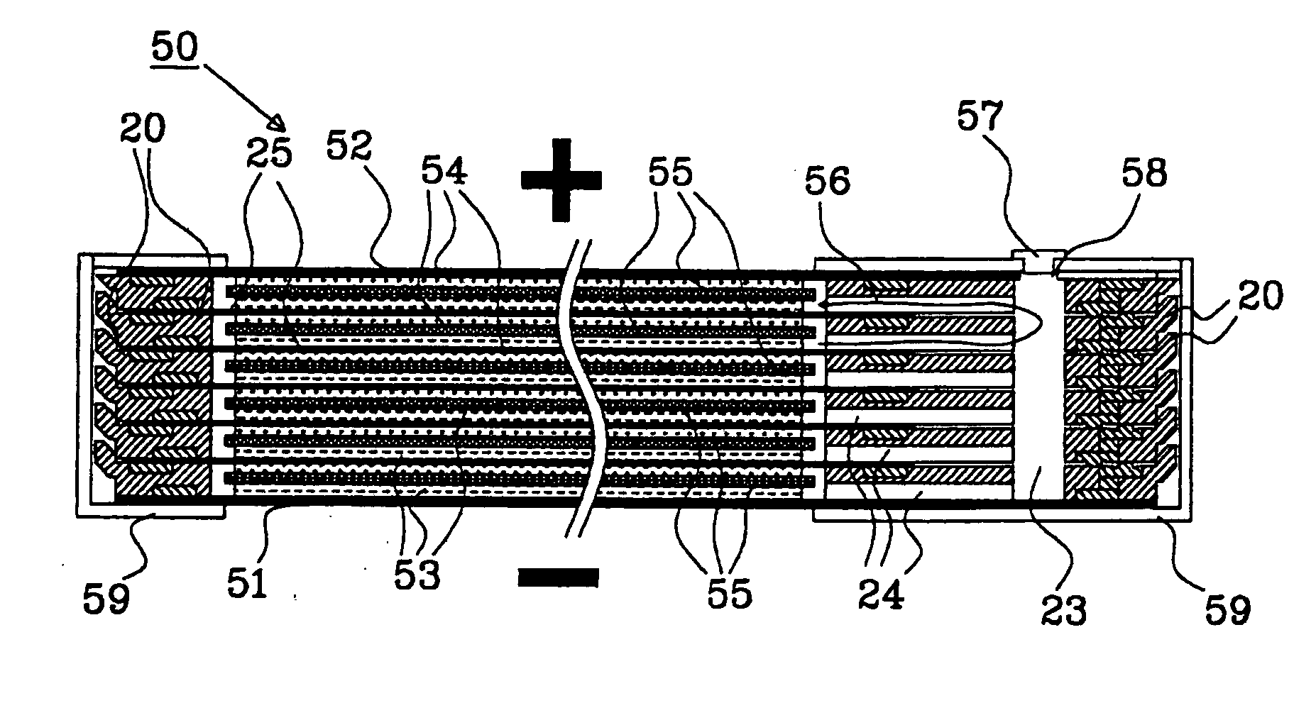
A gasket 20; 40; 80 for use in a starved electrolyte bipolar battery comprises a structural part 27; 44; 82 in the shape of a frame having an upper surface 1 and a lower surface 2, and at least one channel 23, 24; 83, 84 to permit gas passage through the gasket. The structural part is made from a first material having hydrophobic properties. The gasket 20; 40; 80 further comprises at least a first sealing surface 30; 47; 91 arranged in a closed loop projecting from the upper surface 1, and at least a second sealing surface 30; 47; 92 arranged in a closed loop projecting from the lower surface 2. The first and the second sealing surfaces are provided on at least one sealing part 26; 41, 41; 81, are made from a second material, and the first material of the structural part 27; 44; 82 has a higher elastic modulus than an elastic modulus of the second material of the sealing parts 26; 41, 42; 81. A starved electrolyte bipolar battery and a method for manufacturing a gasket are also disclosed.

Description

CROSS REFERENCE TO RELATED APPLICATION [0001] This US non-provisional application is a Continuation-in-Part of U.S. application Ser. No. 10 / 712,018, filed Nov. 14, 2003, the content of which is incorporated herein by reference.BACKGROUND [0002] 1. Technical Field [0003] Example embodiments relate to a gasket, and a bipolar battery including at least one gasket. Example embodiments also relate to a method for manufacturing a gasket. [0004] 2. Description of Related Art [0005] A bipolar battery construction comprises an electrically conductive bipolar layer (or “biplate”) that serves as an electrical interconnection between adjacent cells in the battery as well as a partition between the cells. In order for the bipolar construction to be successfully utilized, the biplate should be sufficiently electronically conductive to transmit current from cell to cell, chemically stable in the cell's environment, capable of making and maintaining good contact to the electrodes, capable of being ...

Claims


Application Information

Patent Timeline
Patent Type & Authority Applications(United States)
IPC IPC(8): H01M2/18F16J15/02H01M6/00H01M6/42H01M10/04H01M10/30H01M10/34H01M50/186H01M50/193H01M50/609
CPCH01M2/08Y10T29/4911H01M2/36H01M4/24H01M4/80H01M6/42H01M10/04H01M10/0418H01M10/044H01M10/282H01M10/287H01M10/30H01M10/345H01M10/347H01M2004/029Y02E60/124Y10T29/49108H01M2/12Y02E60/10H01M50/30Y02P70/50H01M50/193H01M50/186H01M50/609
Inventor HOCK, DAVIDFREDRIKSSON, LARSPUESTER, NEIL H.
Owner NILAR INT AB
Learn More